The Raspberry Pi Pico is a compact yet powerful piece of hardware. It is built with the dual-core RP2040 microcontroller, which features 2MB of Flash memory (expandable to 16MB) and 264KB of SRAM. These specifications make the Pico suitable for a broad range of applications, from hobby projects to industrial uses.
In this article/video, I demonstrate how I used a Raspberry Pi Pico, a digital SHTC3 sensor, and a 2.4” color TFT display to create a graphical temperature and humidity monitoring/control unit. This system is ideal for monitoring environments like homes, offices, indoor gardens, or various devices. Additionally, the board is equipped with two relays that enable users to set cooling/heating thresholds and adjust parameters via a graphical interface.
The most challenging part of this project was coding the Pico. I used the Pico C/C++ SDK and dedicated a significant amount of time to designing the graphical user interface and debugging the code. It wasn’t an easy task, but ultimately, it was very rewarding.
For the schematic and PCB design, I used Altium Designer 22 and added missing component libraries through Altium’s manufacturer part search. By using the Octopart website, I was able to quickly gather component information and generate the Bill of Materials (BOM). Finally, I sent the Gerber files to Wellcircuits for high-quality PCB fabrication.
This is a fantastic piece of hardware for anyone interested in electronics, so let’s dive in! 🙂
To order a fully assembled PCB board (FREE shipping), please contact: info@wellcircuits.com
Specifications
Input Power: 7.5V to 9V (max)
Current Consumption: 280mA (max)
Temperature Range: -40°C to 125°C
Temperature Tolerance: +/-0.2°C
Humidity Range: 0%RH to 100%RH
Humidity Tolerance: +/-2%RH
Output Relay Control: Temperature
Screen Size: 2.4” color display (320×240)
A: Circuit Analysis
The circuit diagram for the device is divided into two main sections: the main circuit and the panel circuit. Figure 1 shows the schematic for the mainboard, and Figure 2 shows the schematic for the panelboard. I used Altium Designer to design both the schematic and PCB.
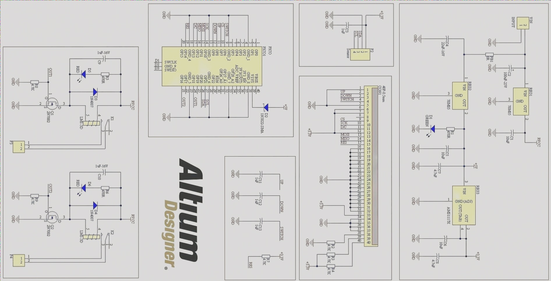
Figure 1
Schematic diagram of the temperature and humidity monitoring and control unit (main circuit)
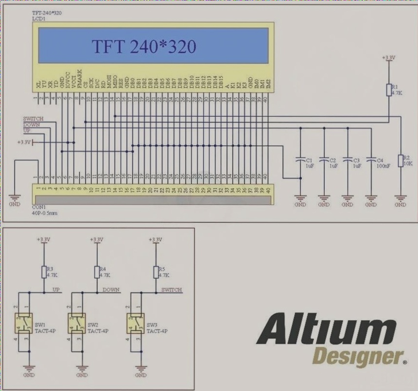
Figure 2
Schematic diagram of the temperature and humidity monitoring and control unit (panel circuit)
A-1: Main Circuit
The main circuit consists of three key sections: the power supply, the Pico board, and the relays. Let’s look at each part in detail.
A-1-1: Power Supply
VIN is a two-pin XH connector used to supply power to the board. The input voltage range is between 7.5V and 9V. REG1 is a 78M05 +5V regulator that powers the relays. The maximum current draw for this section is 100mA, since both relays are not activated simultaneously. However, each relay draws 90mA to 100mA when active. Capacitors C1 and C2 reduce input and output noise.
The combination of FB1 (zero-ohm ferrite bead) and C4 reduces voltage noise on the input, as the supply for the relays and the rest of the board should be isolated. REG2 is another 78M05 regulator that provides a +5V supply for the processor, sensor, and TFT display.
D1 is an LED that indicates a proper supply connection, and capacitors C5, C6, C7, and C8 further reduce noise. REG3 is an AMS1117-3.3V regulator that provides a stable +3.3V rail for the Pico, SHTC3 sensor, and TFT display.
A-1-2: Pico Board
I used the default Raspberry Pi Pico board for this project (Pico1). The board has 2MB of flash memory. Figure 3 shows an image of the Pico board.
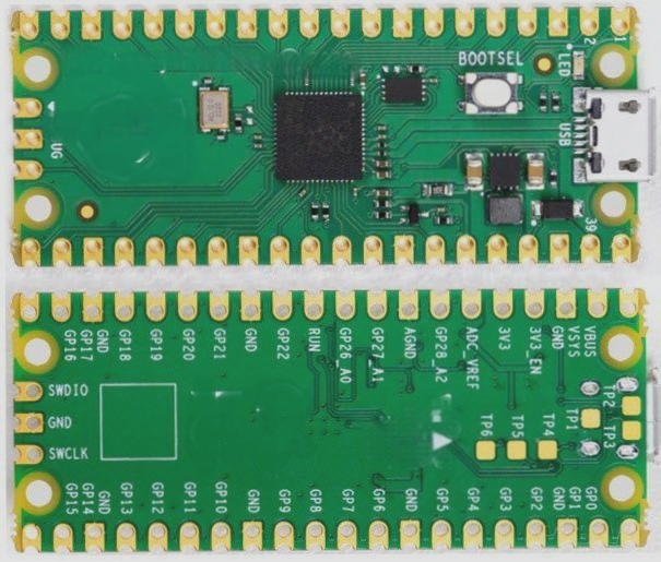
Figure 3
Raspberry Pi Pico board (2MB Flash)
According to the Raspberry Pi Pico datasheet, the easiest way to power the Pico without a USB connection is using a Schottky diode (D2). A diode introduces a forward voltage drop, but since the input voltage is +5V, it does not cause any issues. A series diode is an ideal solution for this application. Capacitors C11, C12, and C13 mitigate the debouncing effect and reduce noise from the tactile pushbuttons. I placed these capacitors as close as possible to the Pico pins. R7 is a pull-up resistor for the reset pin (active-low reset for the LCD). P2 is the connector for the SHTC3 sensor, and C3 is a decoupling capacitor. CON1 is a 40-pin FPC connector that links the panelboard and mainboard.
A-1-3: Relays
P3 and P4 are power connectors for the heater and cooler, respectively. K1 and K2 are LM1-5D relays. Q1 and Q2 are 2N7002 MOSFETs used to control the relays, and D3 and D4 protect the MOSFETs from reverse currents generated by the relay coils. R8 and R9 are pull-down resistors to prevent unintended triggering of the MOSFETs. D5 and D6 are LEDs that indicate when the relays are active. C9 and C10 reduce noise during relay activation and deactivation.
A-2: Panel Circuit
CON1 and LCD1 are 40-pin FPC connectors. CON1 links the mainboard and panelboard. Capacitors C1 to C4 filter supply noise. R1 is a pull-up resistor for the CS (chip select) pin, as this pin is active-low. R2 is a pull-down resistor for the MISO pin to reduce noise on the high-speed SPI bus. R3, R4, and R5 are pull-up resistors for the SW1, SW2, and SW3 tactile pushbuttons.
B. PCB Layout

