—
**Precautions for the Clock on a Single PCB Board**
1. **Layout**
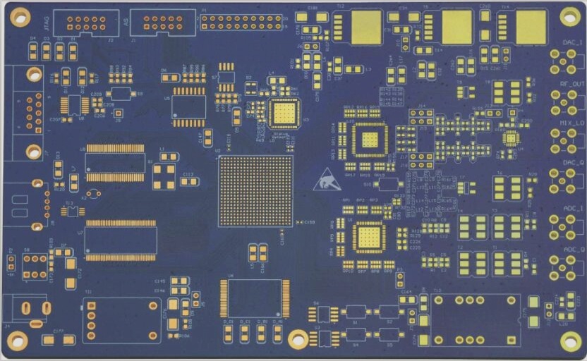
1) The clock crystal and associated circuits should be positioned centrally on the PCB, ideally over a solid ground plane, and kept away from I/O interfaces. The clock generation circuit should not be implemented on a daughter card or separate board; instead, it must be incorporated on a dedicated clock board or carrier board.
2) Only place devices related to the clock circuit within the designated clock circuit area of the PCB. Avoid routing other circuits or signal lines near or underneath the crystal. Utilize a ground plane beneath the clock generation circuit and crystal. Allowing other signals to pass through this ground plane can disrupt its function, creating small ground loops that can affect the continuity of the ground plane and cause issues at high frequencies.
3) Consider implementing shielding measures for clock crystals and associated circuits.
4) If the clock casing is metallic, ensure that a copper area is placed under the crystal on the PCB, with a solid electrical connection to the complete ground plane via porous grounding.
2. **The Benefits of a Ground Plane Under the Clock Crystal**
The circuit within the crystal oscillator generates radio frequency currents. If the crystal is housed in a metal casing, the DC power pin serves as a reference for both the DC voltage and RF current loop within the crystal. The transient current generated by the RF radiation of the casing is released through the ground plane. Essentially, the metal casing acts as a single-ended antenna, and a nearby image plane or ground plane—often multiple layers—helps to manage RF radiation coupling to the PCB ground loop. Additionally, the ground plane aids in heat dissipation and provides an image plane that reduces common mode currents generated by the crystal and clock circuit, thereby mitigating RF radiation. The ground plane also absorbs differential mode RF currents and must be connected to a complete ground plane through multiple vias to ensure low impedance. The clock generation circuit should be positioned close to this ground plane. SMT-packaged crystals, which are typically plastic, tend to radiate more RF energy than metal-cased crystals, as RF currents within the crystal are more likely to radiate into space and couple with other components.
3. **Shared Clock Traces**
For signals with fast rising edges and clock signals, a radial topology connection is preferable over a single common drive source network. Ensure each trace is routed according to its characteristic impedance.
4. **Clock Transmission Line Requirements and PCB Layering**
The principle for clock routing is to place a complete image plane layer adjacent to the clock routing layer, minimize the routing length, and control impedance.
5. **Issues with Incorrect Cross-Layer Traces and Impedance Mismatches**
1) Using vias and jumps in traces can disrupt the completeness of the image PCB ground loop.
2) Variations in voltage on the signal pin of a device can cause surge voltages on the image plane.
3) Failure to follow the 3W principle in routing can lead to crosstalk between different clock signals.
6. **Routing the Clock Signal**
1) Clock lines should be routed on the inner layers of a multi-layer PCB, preferably as strip lines. If routing on the outer layer, use microstrip lines.
2) Routing on inner layers ensures a complete image plane, providing a low impedance RF transmission path and allowing magnetic flux to counteract the flux from the source transmission line. The closer the source and return paths, the better the degaussing. Each complete planar image layer in a high-density PCB can offer 6-8 dB of rejection.
3) Advantages of a Multi-Layer PCB for Clock Routing: Dedicated layers for power and ground planes enhance decoupling, reduce ground loop area, minimize differential mode radiation, and lower EMI. Consistent trace impedance is maintained throughout, reducing crosstalk between adjacent traces.
—


