The Difference Between PCB Hard Boards and FPC Soft Boards
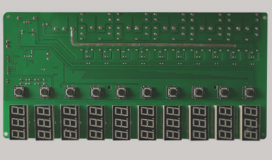
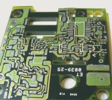
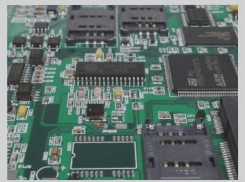
When it comes to circuit boards, there are distinct categories: PCB hard boards and FPC soft boards. PCB stands for Printed Circuit Board, while FPC or FPCB represents Flexible Printed Circuit Board. A combination of these two types results in the creation of Rigid-Flex Printed Circuit Boards (RFPC or RFPCB), offering a unique blend of characteristics from both hard and soft boards.
PCB hard boards are thick and sturdy, designed for electronic component installation and mechanical durability. On the other hand, FPC soft boards are thin, lightweight, and flexible, making them ideal for three-dimensional installations. The emergence of Rigid-Flex boards allows for localized bending, providing versatility in circuit board design.
Advancements in the electronics industry are driving the need for more precise and densely packed circuit board designs. Manual inspection methods are no longer sufficient to meet production demands, leading to a shift towards automated defect detection in FPCs.

FPC Manufacturer’s Soft Board Soldering Process
Manufacturers of FPCs commonly employ manual soldering processes for soft boards. Two primary techniques include tin press welding and manual drag welding, with tin press welding being preferred for its smooth joints and reduced defect rates. However, manual drag soldering remains a cost-effective option, requiring careful component layout consideration during board design.
The key steps in FPC welding involve paste alignment, tin delivery, drag welding, visual inspection, and electrical testing. Proper alignment of FPC pads and solder surfaces, along with optimal soldering parameters such as time, temperature, tin delivery position, and strength, are crucial for successful solder connections.
Control parameters for FPC manufacturers’ soft boards include resting the soldering iron on the pad for 2-3 seconds before soldering, maintaining a 30-degree angle relative to the gold finger, and adhering to specific time, temperature, tin delivery position, and strength guidelines during soldering and drag welding processes.


