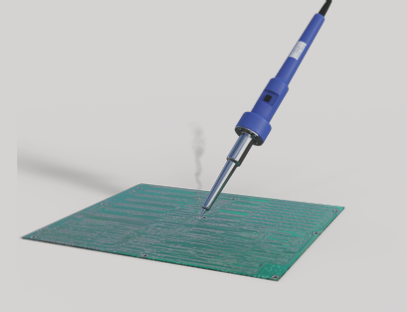
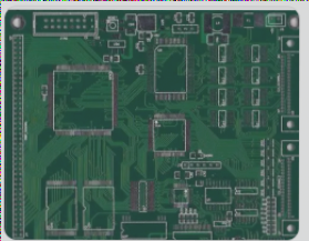
1. The difference between soldering FPC and PCB
As the smart wearable industry continues to grow, assembling components on FPC flexible circuit boards has become essential. Due to space constraints, the surface mounting of SMD on FPC is emerging as a key trend in SMT technology. However, FPC is inherently more challenging to assemble than PCB, as it lacks the same structural rigidity. Today, let’s explore the distinctions between flexible boards and rigid boards.
2. The welding process
Similar to the PCB process, solder paste is applied to the FPC and rigid-flex boards using a stencil and solder paste printer. However, since the surface of FPC is not flat, we must employ fixing devices or reinforcements for stabilization. Typically, reinforcements are adhered to the component areas of the FPC.
3. SMT component placement

1. Under the current trend of miniaturization in SMT components, small parts can pose various challenges during the reflow soldering process. When dealing with smaller FPCs, issues such as extension and wrinkling may not be critical, allowing for a reduction in SMT frame size or an increase in marking points. If you prefer not to attach a stiffener to the base of the component, flexibility after assembly becomes essential. In this case, an SMT fixture would be an ideal solution.
2. Reflow soldering process
Before reflow soldering, it is crucial to dry the FPC. This marks a significant difference from the PCB component placement process. Beyond the dimensional instability of flexible materials, they also exhibit high hygroscopicity, absorbing moisture akin to sponges. Once the FPC absorbs moisture, reflow soldering must be halted. While PCBs face similar challenges, they possess a higher tolerance. FPCs require preheating and baking at temperatures ranging from 225° to 250°. This preheating and baking must be executed promptly within one hour. If not completed in time, the FPC should be stored in a dry or nitrogen environment.
3. FPC mold
What does the flexible circuit board mold entail, and why is mold creation necessary? How many types of molds exist for flexible circuit boards, and how do you select an appropriate mold? Today, we will explore the details of flexible circuit board molds. FPC molds are primarily utilized for cutting the shape and cover layer of FPCs.
For sample production, laser molding is commonly employed to reduce costs and time for customers. Since updated versions render molds obsolete, laser cutting machines are used for shaping and layering. However, the production lead time for laser cutting is generally longer than that for contour cutting tools, which necessitates mold creation for mass production. Typically, there are four types of molds used in our production process:
1. **Standard mold**: This is the most frequently utilized mold for cutting the cover layers and shapes of most flexible circuit boards. The appearance tolerance for the FPC is 0.1mm, while the tolerance range for gold fingers can be maintained within 0.15mm.
2. **Medium-sized screen printing mold**: This mold offers high precision and a longer lifespan, with a punching capacity of around 200,000 times. The results are visually appealing and smooth, with a tolerance of 0.07mm. However, the cost is higher, and the mold fabrication time is longer compared to standard molds.
3. **Precision mold**: Characterized by a very smooth surface, this mold is utilized for flexible circuit boards that demand stringent tolerances. The tolerance for gold fingers can be controlled within ±0.05mm. However, the associated costs are significantly higher than those for standard molds.
4. **Knife mold**: Typically employed to cut simple flexible circuit boards, this mold is suitable for flexible circuit boards exceeding 500mm in length and for adhesives. The tolerance is approximately ±0.2mm.
—
Let me know if you need any further adjustments!
As the smart wearable industry continues to grow, assembling components on FPC flexible circuit boards has become essential. Due to space constraints, the surface mounting of SMD on FPC is emerging as a key trend in SMT technology. However, FPC is inherently more challenging to assemble than PCB, as it lacks the same structural rigidity. Today, let’s explore the distinctions between flexible boards and rigid boards.
2. The welding process
Similar to the PCB process, solder paste is applied to the FPC and rigid-flex boards using a stencil and solder paste printer. However, since the surface of FPC is not flat, we must employ fixing devices or reinforcements for stabilization. Typically, reinforcements are adhered to the component areas of the FPC.
3. SMT component placement

1. Under the current trend of miniaturization in SMT components, small parts can pose various challenges during the reflow soldering process. When dealing with smaller FPCs, issues such as extension and wrinkling may not be critical, allowing for a reduction in SMT frame size or an increase in marking points. If you prefer not to attach a stiffener to the base of the component, flexibility after assembly becomes essential. In this case, an SMT fixture would be an ideal solution.
2. Reflow soldering process
Before reflow soldering, it is crucial to dry the FPC. This marks a significant difference from the PCB component placement process. Beyond the dimensional instability of flexible materials, they also exhibit high hygroscopicity, absorbing moisture akin to sponges. Once the FPC absorbs moisture, reflow soldering must be halted. While PCBs face similar challenges, they possess a higher tolerance. FPCs require preheating and baking at temperatures ranging from 225° to 250°. This preheating and baking must be executed promptly within one hour. If not completed in time, the FPC should be stored in a dry or nitrogen environment.
3. FPC mold
What does the flexible circuit board mold entail, and why is mold creation necessary? How many types of molds exist for flexible circuit boards, and how do you select an appropriate mold? Today, we will explore the details of flexible circuit board molds. FPC molds are primarily utilized for cutting the shape and cover layer of FPCs.
For sample production, laser molding is commonly employed to reduce costs and time for customers. Since updated versions render molds obsolete, laser cutting machines are used for shaping and layering. However, the production lead time for laser cutting is generally longer than that for contour cutting tools, which necessitates mold creation for mass production. Typically, there are four types of molds used in our production process:
1. **Standard mold**: This is the most frequently utilized mold for cutting the cover layers and shapes of most flexible circuit boards. The appearance tolerance for the FPC is 0.1mm, while the tolerance range for gold fingers can be maintained within 0.15mm.
2. **Medium-sized screen printing mold**: This mold offers high precision and a longer lifespan, with a punching capacity of around 200,000 times. The results are visually appealing and smooth, with a tolerance of 0.07mm. However, the cost is higher, and the mold fabrication time is longer compared to standard molds.
3. **Precision mold**: Characterized by a very smooth surface, this mold is utilized for flexible circuit boards that demand stringent tolerances. The tolerance for gold fingers can be controlled within ±0.05mm. However, the associated costs are significantly higher than those for standard molds.
4. **Knife mold**: Typically employed to cut simple flexible circuit boards, this mold is suitable for flexible circuit boards exceeding 500mm in length and for adhesives. The tolerance is approximately ±0.2mm.
—
Let me know if you need any further adjustments!

