Interconnection Methods for Circuit Boards
Electronic components rely on electrical contacts for functionality, and the process of establishing these connections is known as interconnection. Printed circuit boards (PCBs) are essential components of electronic devices but require external connections to function properly. Choosing the right interconnection method is crucial in PCB design to ensure reliability, manufacturability, and cost-effectiveness.
Soldering Method
The soldering method is widely used for interconnecting components on a PCB due to its simplicity, low cost, and high reliability. While it ensures stable electrical connections over time, soldering can make maintenance and interchangeability challenging as components are permanently fixed to the board.
For components with fewer external leads and minimal adjustments, soldering is a cost-effective and reliable choice. It is best suited for static applications prioritizing long-term stability over flexibility.
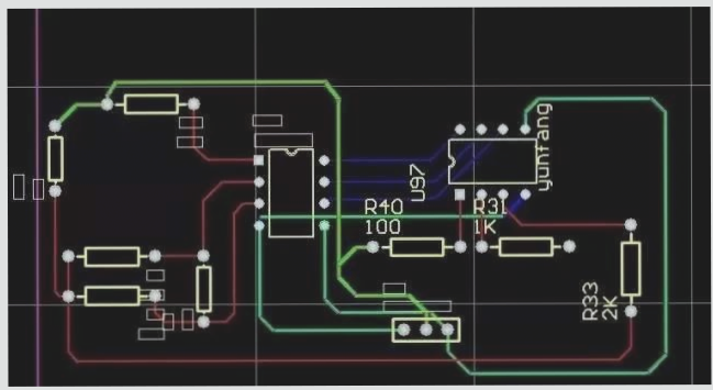
PCB Wire Soldering
PCB wire soldering involves directly connecting components or external parts to the PCB using wires, eliminating the need for connectors. This method is commonly used in devices like radios for connecting speakers and battery boxes.
- Pad Placement and Size: Position solder pads close to the PCB edge with uniform sizes for easy soldering and maintenance.
- Improved Mechanical Strength: Reinforce solder joints to prevent wire tension damage by using through-hole techniques.
- Wire Management: Neatly arrange and secure wires to ensure long-term reliability.
PCB Cable Soldering
Using a flat cable to connect two PCBs offers a reliable and flexible connection, especially when boards need to be connected at a 90-degree angle, creating a rigid assembly.
Connector-Based PCB Interconnection
In complex electronic systems, connectors are commonly used for interconnecting PCBs, providing advantages such as mass production efficiency and simplified maintenance.
- Mass Production Efficiency: Connectors ease assembly and quality control, reducing production costs.
- Simplified Maintenance: Quick identification and replacement of faulty boards reduce downtime and improve system uptime.
PCB Printed Board Socket Connection
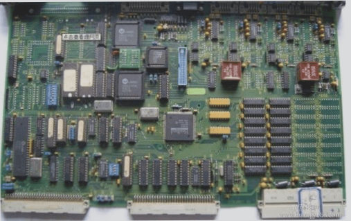
This method, common in complex devices, involves designing a printed plug at the PCB edge that fits into a corresponding socket. The socket design considers factors like contact number, pin spacing, and positioning holes. Gold-plating the plug section enhances wear resistance and reduces contact resistance.
Advantages and Disadvantages of PCB Socket and Pin Connections
- Ease of Assembly: The connection is simple to assemble and offers good interchangeability, making it suitable for mass production.
- Maintenance-Friendly: Faulty boards can be quickly replaced, improving overall system maintainability.
Disadvantages:
- Cost and Precision: This method increases the cost of manufacturing and requires precise PCB design and fabrication.
- Reliability Issues: The contact areas (plug and socket) may suffer from oxidation or wear over time, reducing the connection’s reliability. To address this, it is common to use parallel wire leads or multiple contacts to improve the connection’s integrity.
Socket connections are typically used in multi-board systems and come in two main types: reed-type and pin-type, each offering different mechanical properties for interconnecting PCBs.
Standard Pin Connection
Standard pin connections are commonly used for external connections in smaller instruments. The two PCBs are connected through standard pins, which are typically arranged either parallel or perpendicular to each other.
Benefits of pin connections:
- Simplified Mass Production: Standard pins allow for easy and cost-effective assembly, making this method ideal for smaller devices that require high-volume production.
In summary, the choice of interconnection method—whether wire soldering, cable soldering, or using connectors—depends on the complexity, durability requirements, and production scale of the electronic device. Each method has its own advantages and limitations, and understanding these trade-offs is essential for designing reliable and efficient PCB systems.

