The two most critical processes that contribute to the successful repair of SMT are also the two most commonly overlooked issues:
1. Properly preheating the PCB before reflow.
2. Rapid cooling of solder joints after reflow.
These fundamental processes are often neglected by repair technicians, and as a result, sometimes the condition after repair ends up being worse than before. While some “rework” defects may be detected by subsequent process inspectors, most of these issues remain hidden until they manifest during circuit testing.
**1. Preheating – A Prerequisite for Successful Repair**
It’s well-known that exposing a PCB to high temperatures (315–426°C) for extended periods can introduce many potential problems, including thermal damage such as pad and lead warping, substrate delamination, white spots, blistering, and discoloration. Warped or burnt boards typically catch the attention of inspectors. However, just because a PCB does not exhibit visible signs of “burning” does not mean it is free from damage. The “invisible” damage caused by high temperatures can often be even more severe than the issues mentioned above. Decades of testing have repeatedly shown that PCBs and their components may pass inspection and testing after rework, but their performance degrades at a faster rate compared to normal PCBs. These “hidden” problems, such as internal warping of the substrate or degradation of circuit components, arise from the differing thermal expansion coefficients of the materials involved. Clearly, these issues are not immediately apparent, even during circuit testing, but they remain latent within the PCB assembly.
Although a repair may look fine at first glance, it’s akin to the saying: “The surgery was successful, but the patient unfortunately passed away.” The cause of significant thermal stress occurs when PCB components, at room temperature (21°C), are suddenly subjected to a heat source such as a soldering iron, desoldering tool, or hot air gun, typically reaching temperatures around 370°C. This creates a temperature differential of approximately 349°C between the PCB and its components, which can lead to the “popcorn” effect.
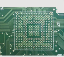
Where is the key technology in PCB rework?
The “popcorn” phenomenon refers to the occurrence where moisture trapped inside an integrated circuit or SMD component rapidly heats up during the repair process. This rapid heating causes the moisture to expand, leading to micro-cracking or even cracking of the component. To avoid this, both the semiconductor and PCB manufacturing industries recommend minimizing the preheating time before reflow and quickly reaching the desired reflow temperature. In reality, the reflow process of PCB components already involves a preheating phase before the actual reflow. Regardless of whether a PCB factory uses wave soldering, infrared (IR) vapor phase soldering, or convection reflow soldering, each method typically requires preheating or thermal conditioning. This preheating generally takes place at temperatures between 140°C and 160°C. A brief, controlled preheating of the PCB before reflow has proven effective in solving many issues during rework. This approach has been successfully used in reflow soldering processes for years. As a result, preheating a PCB assembly before reflow offers numerous advantages.
Since preheating the board lowers the reflow temperature, methods like wave soldering, IR/vapor phase soldering, and convection reflow soldering can all operate at around 260°C.
### 3. The Multifaceted Benefits of Preheating
First, preheating, or “thermal conditioning,” of components before reflow helps activate the flux, removes oxides and surface films from the metal surfaces to be soldered, and drives off volatiles from the flux. This cleaning effect, brought about by the activation of the flux right before reflow, improves the wetting action during soldering. Preheating involves heating the entire assembly to a temperature just below the melting point of the solder and the reflow temperature. This helps to significantly reduce the risk of thermal shock to both the substrate and its components. Rapid heating, without preheating, would increase the temperature gradient across the component, which can result in thermal shock. Such large temperature gradients create thermo-mechanical stress, which can cause materials with low thermal expansion rates to become brittle, crack, or even fail. SMT chip resistors and capacitors, in particular, are especially susceptible to thermal shock.
Additionally, in PCB design, preheating the entire assembly allows for a reduction in both reflow temperature and reflow time. Without preheating, the only alternative is to either increase the reflow temperature or extend the reflow time. Both of these approaches are undesirable and should be avoided.
If you have any PCB manufacturing needs, please do not hesitate to contact me.Contact me

