When designing a PCB (Printed Circuit Board), the size plays a critical role in ensuring both functionality and cost-effectiveness. A larger PCB increases the length of the printed traces, which in turn raises the impedance, reduces the noise immunity, and escalates manufacturing costs. On the other hand, a PCB that is too small can result in poor heat dissipation and increased susceptibility to interference due to tightly packed components. After finalizing the PCB size, the next step is to strategically position special components, followed by organizing the remaining components based on the circuit’s functional requirements.
### Key Considerations for Component Placement
1. **Minimize High-Frequency Trace Lengths**
When placing high-frequency components, the goal is to minimize the length of the connecting traces. Longer traces increase the impedance and can amplify noise, which leads to potential performance degradation. Reducing the length of the traces also minimizes parasitic inductance and capacitance, thus mitigating electromagnetic interference (EMI). Furthermore, components sensitive to interference should not be placed too close to high-frequency parts. Keeping input and output components at opposite ends of the PCB will also help reduce noise coupling and signal degradation.
2. **Maintain Adequate Spacing for High-Potential Components**
Certain components, such as high-voltage parts or circuits with significant potential differences, require special attention. It is important to maintain sufficient distance between such components and traces to prevent unintentional short circuits due to discharge. To ensure safety, high-voltage components should be placed in locations that are not easily accessible during the debugging process. This precaution helps avoid accidental contact during handling or troubleshooting.
By adhering to these principles, you can optimize the PCB design for performance, reliability, and safety. Careful component placement not only improves signal integrity but also enhances the overall efficiency of the circuit.

**3. Component Mounting and Thermal Management:**
1. **Heavy Components**: Components weighing over 15g should be secured with brackets before soldering. For large, heavy components that also generate significant heat, avoid placing them directly on the PCB. Instead, they should be mounted on the chassis’ bottom plate. Ensure that the thermal management of these components is carefully planned, keeping heat-sensitive parts at a safe distance from high-heat components.
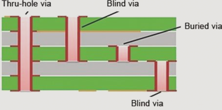
2. **Thermal Considerations**: When designing, it’s critical to place heat-generating components far from each other to prevent thermal interference. Additionally, effective heat dissipation solutions, like heat sinks or thermal vias, should be considered to maintain system stability.
**4. Adjustable Components Layout:**
For adjustable components such as potentiometers, inductance coils, variable capacitors, and micro switches, their placement should take into account the overall system’s structural requirements:
1. **Internal Adjustments**: If adjustments are to be made inside the device, ensure these components are positioned where they are easily accessible for user adjustments, preferably on the PCB itself.
2. **External Adjustments**: For components adjusted outside the device, position them such that they align with the adjustment knobs on the chassis panel, ensuring ease of use and ergonomics for the end user.
**5. Positioning Holes and Brackets:**
Ensure that the PCB design reserves appropriate space for positioning holes and brackets to secure the board within the device. Proper placement of these holes is crucial for mechanical stability and alignment during assembly.
**2. PCB Layout and Anti-Interference Design:**
1. **Functional Unit Placement**: Arrange the circuit components based on the functional flow of the circuit. This promotes efficient signal circulation and minimizes the risk of interference. Try to align signals in the same direction to reduce cross-talk.
2. **Component Distribution**: Begin layout by centering the core components of each functional circuit. Surround these components with others, ensuring the arrangement is neat, compact, and organized. This helps reduce the complexity of wiring and makes soldering easier, particularly in mass production.
3. **High-Frequency Circuit Considerations**: For circuits that operate at high frequencies, account for the parasitic elements between components. Components should be arranged as symmetrically as possible to minimize inductance and capacitance effects. This not only enhances performance but also simplifies assembly.
4. **Edge Clearance**: Ensure that components along the PCB edges are spaced at least 2mm from the board’s perimeter. Additionally, choose a rectangular PCB shape, ideally with a length-to-width ratio of 3:2 or 4:3. For boards larger than 200mm x 150mm, the mechanical strength of the board should be reviewed to prevent warping or failure during use.
**General PCB Design Principles:**
The PCB serves as the foundation for all the circuit components in an electronic device. Even if the circuit schematic is correctly designed, poor PCB design can lead to significant reliability issues. When designing a PCB, it’s crucial to follow established design principles, particularly in the areas of layout, thermal management, and anti-interference, to ensure optimal performance and longevity of the electronic product.
### Key Considerations for Component Placement
1. **Minimize High-Frequency Trace Lengths**
When placing high-frequency components, the goal is to minimize the length of the connecting traces. Longer traces increase the impedance and can amplify noise, which leads to potential performance degradation. Reducing the length of the traces also minimizes parasitic inductance and capacitance, thus mitigating electromagnetic interference (EMI). Furthermore, components sensitive to interference should not be placed too close to high-frequency parts. Keeping input and output components at opposite ends of the PCB will also help reduce noise coupling and signal degradation.
2. **Maintain Adequate Spacing for High-Potential Components**
Certain components, such as high-voltage parts or circuits with significant potential differences, require special attention. It is important to maintain sufficient distance between such components and traces to prevent unintentional short circuits due to discharge. To ensure safety, high-voltage components should be placed in locations that are not easily accessible during the debugging process. This precaution helps avoid accidental contact during handling or troubleshooting.
By adhering to these principles, you can optimize the PCB design for performance, reliability, and safety. Careful component placement not only improves signal integrity but also enhances the overall efficiency of the circuit.
**3. Component Mounting and Thermal Management:**
1. **Heavy Components**: Components weighing over 15g should be secured with brackets before soldering. For large, heavy components that also generate significant heat, avoid placing them directly on the PCB. Instead, they should be mounted on the chassis’ bottom plate. Ensure that the thermal management of these components is carefully planned, keeping heat-sensitive parts at a safe distance from high-heat components.
2. **Thermal Considerations**: When designing, it’s critical to place heat-generating components far from each other to prevent thermal interference. Additionally, effective heat dissipation solutions, like heat sinks or thermal vias, should be considered to maintain system stability.
**4. Adjustable Components Layout:**
For adjustable components such as potentiometers, inductance coils, variable capacitors, and micro switches, their placement should take into account the overall system’s structural requirements:
1. **Internal Adjustments**: If adjustments are to be made inside the device, ensure these components are positioned where they are easily accessible for user adjustments, preferably on the PCB itself.
2. **External Adjustments**: For components adjusted outside the device, position them such that they align with the adjustment knobs on the chassis panel, ensuring ease of use and ergonomics for the end user.
**5. Positioning Holes and Brackets:**
Ensure that the PCB design reserves appropriate space for positioning holes and brackets to secure the board within the device. Proper placement of these holes is crucial for mechanical stability and alignment during assembly.
**2. PCB Layout and Anti-Interference Design:**
1. **Functional Unit Placement**: Arrange the circuit components based on the functional flow of the circuit. This promotes efficient signal circulation and minimizes the risk of interference. Try to align signals in the same direction to reduce cross-talk.
2. **Component Distribution**: Begin layout by centering the core components of each functional circuit. Surround these components with others, ensuring the arrangement is neat, compact, and organized. This helps reduce the complexity of wiring and makes soldering easier, particularly in mass production.
3. **High-Frequency Circuit Considerations**: For circuits that operate at high frequencies, account for the parasitic elements between components. Components should be arranged as symmetrically as possible to minimize inductance and capacitance effects. This not only enhances performance but also simplifies assembly.
4. **Edge Clearance**: Ensure that components along the PCB edges are spaced at least 2mm from the board’s perimeter. Additionally, choose a rectangular PCB shape, ideally with a length-to-width ratio of 3:2 or 4:3. For boards larger than 200mm x 150mm, the mechanical strength of the board should be reviewed to prevent warping or failure during use.
**General PCB Design Principles:**
The PCB serves as the foundation for all the circuit components in an electronic device. Even if the circuit schematic is correctly designed, poor PCB design can lead to significant reliability issues. When designing a PCB, it’s crucial to follow established design principles, particularly in the areas of layout, thermal management, and anti-interference, to ensure optimal performance and longevity of the electronic product.