1. Eliminating PCB design defects is a common challenge faced by PCB manufacturers. One such issue is traces being too close together, which can lead to solder bridges. These bridges may form underneath components, making them difficult to detect. Poor solder joints also present a significant problem, often caused by insufficient or no electrical connection between copper pads and components. Both issues require thorough inspection and continuity testing to identify. Ensure you have adequate desoldering braid on hand and remove excess solder from pins, especially in tight spaces.
2. Certain circuits are more sensitive to PCB design than others. Long traces carrying high current or high-speed signals are more prone to issues caused by imperfect solder joints. Components themselves can also be the source of problems; even new parts may have defects. If components are exposed to excessive heat during soldering, they can be damaged over time. For surface-mount components, proper alignment is critical, particularly for those with heat dissipation pads on their bottom. These pads usually need to be electrically connected, and if clearance is inadequate or alignment is off, solder bridges can form.
3. Hand-soldered PCBs are more challenging to assemble correctly, as they may have thin traces or soldering issues that lead to poor connections. Professionally manufactured and soldered boards, on the other hand, simplify assembly and reduce the risk of solder bridges or poor joints. There are various free software tools and companies that can help you detect issues on your circuit board at an affordable cost, often easily found through a Google search. I personally use ExpressPCB and have been very satisfied with the results.
—
The revisions aim to enhance readability while preserving the original technical details and style.
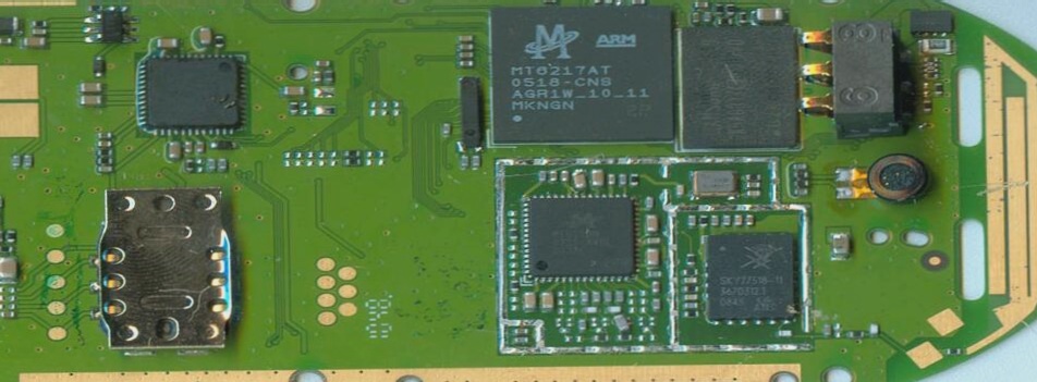
Many printed circuit boards (PCBs) have been handmade, and many professional PCBs have been designed. For simple designs, it’s common to make small mistakes on the blackboard. In most cases, these mistakes can be corrected with a precision knife to make the circuit work with the other components. However, some issues require significant changes to fix. While most PCB designs are successful without requiring a second iteration, nearly every board I’ve created has had something I wanted to adjust. For instance, the role of a major integrated circuit (IC) sometimes deviates from what is stated in the datasheet. One of the voltage regulator outputs was higher than expected, which led to a component being driven with a voltage it couldn’t handle. After correcting this issue, I discovered another opportunity to improve performance and reduce component count, which also freed up space on the PCB. I replaced some connectors with more suitable ones.
The board is approximately 4″ x 3″ and contains over 100 components. Due to the small parts and tight spacing, manual soldering can take several hours. My approach is to install the basic components first, so that the core circuit functions with minimal parts, allowing me to test everything before completing the full soldering process.
One essential chip is a 34-pin oversized package with tight pin pitch and a bottom heat sink. This was the first component I installed. Before adding the other components, I always check continuity. It can take at least 5 minutes to precisely position the chip, as even small errors can cause problems. I minimize the soldering time to avoid overheating the chip. While there are many tiny components to install, the close pin spacing on the chip makes it the most challenging part. Once it’s in place, the rest of the assembly becomes easier.
Although this particular PCB is denser than typical designs, it’s still important to install key components first and perform continuity checks before moving on to other parts. Sometimes, I sacrifice perfect chip placement to avoid the risk of solder bridges.
**Prototype Layout Issues:**
1. **Layout Errors** – Missing traces, insufficient vias.
2. **Layout Problems** – Insufficient trace width, excessive noise, incorrect pad sizes, or improper package outlines.
3. **Assembly Issues** – Problems with mechanical fit, mounting functions, or post-design verification during PCB production. Errors in manufacturing can occur, such as the use of incorrect materials or layer misalignment. Additionally, incorrect parts may be placed in the wrong locations, or leads may be bent. Cold solder joints, missing solder, or incorrect solder mask application are common problems.
4. **Defective Components** – Components may be out of tolerance, poorly marked, or have incorrectly designed edges.
It’s great to get the PCB to work, but once it enters production, it will be exposed to thousands of changes in temperature, pressure, time, and component variations. These can create additional challenges.
1) **Solder Joint Failures:**
a) Cold joints or poor solder connections.
b) Incorrect pad design, causing misalignment between the chip and pad.
2) **Trace Size Issues:** The trace size might exceed the manufacturer’s capabilities. Poor etching can lead to incomplete circuits, or tiny interconnections that cause high resistance in the traces.
3) **Layer-to-Layer Connections:** Problems can arise when through holes are too small, resulting in failed connections between layers.
4) **Grounding Issues:** A poorly designed ground plane or improper ground connections can lead to ground loops. These currents can cause varying “GND” voltages across different parts of the circuit board.
5) **Bypass Capacitor Placement:** If the bypass capacitor is placed too far from the relevant component, it can cause high-frequency noise that destabilizes chip operation, as the chip will experience irregular power input.
6) **High Current on Small Traces:** High current running through small traces can cause the traces to heat up excessively, leading to potential damage.
7) **Cross-Talk Between Traces:** High-frequency signals from one trace can induce unwanted signals on an adjacent trace, causing interference.
If your have any questions about PCB ,please contact me info@wellcircuits.com

