2. Double Sided PCB
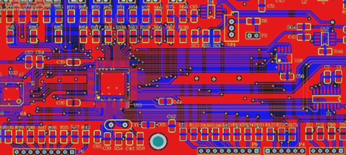
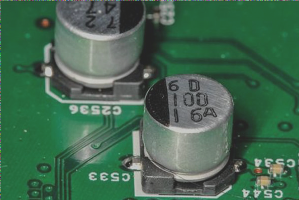
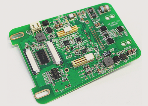
The substrate materials mainly used are Glass Epoxy copper laminate, Glass Composite copper laminate, and paper Epoxy copper laminate. These materials find extensive applications in personal computers, electronic musical instruments, multi-functional telephones, automotive electronic devices, electronic peripherals, and electronic toys. Glass benzene resin copper laminate, known for its excellent high-frequency characteristics, is predominantly employed in communication devices, satellite broadcasting equipment, and mobile communication devices despite its higher cost.
3. 3-4 Layer Multilayer PCB
The substrate materials primarily include Glass Epoxy or benzene resin. This type of PCB is widely used in personal computers, Medical Electronics (Me) equipment, measurement instruments, semiconductor testers, Numeric Control (NC) machines, electronic exchanges, communication devices, memory circuits, and IC cards. Additionally, there are multilayer PCBs using glass composite copper laminates, valued for their exceptional processing properties.
4. 6-8 Layer PCB
The substrate materials continue to be primarily Glass Epoxy or Glass benzene resin. These PCBs are utilized in electronic switches, semiconductor testers, mid-sized personal computers, Engineering Work Stations (EWS), and NC machines among others.
5. PCB with More Than 10 Layers
These PCBs primarily use glass benzene resin or glass epoxy as their substrate material. They serve specialized applications such as large-scale computers, high-speed computers, and communication devices due to their high-frequency and high-temperature characteristics.
6. Other PCB Substrate Materials
Other substrate materials for PCBs include aluminum and iron substrates. These circuits are formed on the base plate and are mostly used in rotary machines (small motors) and automobiles. Additionally, flexible PCBs are made from materials like polymers and polyesters, suitable for single, double, or multi-layer configurations. Flexible PCBs are commonly applied in movable parts of cameras, office automation (OA) equipment, and in effective connections between rigid PCBs or a combination of rigid and flexible PCBs, offering diverse shaping possibilities due to their high elasticity.
7. PCB Heat Dissipation
1) When arranging components, sensitive to temperature, other than temperature sensing devices, should be positioned near the air inlet and upstream of high-power components to minimize thermal impact. If separation isn’t feasible, thermal shielding plates (polished metal sheets with low emissivity) should be used.
2) Heat-generating devices should be placed close to air outlets or on top, unless they require lower operating temperatures, in which case positioning near air inlets is preferable. Ensure staggered placement with other heating elements and thermal sensors in the direction of rising air.
3) Distribute high-power components to avoid concentrated heat sources and evenly arrange components of different sizes to ensure uniform airflow resistance and volume.
4) Align vents with components needing high heat dissipation.
5) Place taller components behind shorter ones and arrange them to minimize airflow resistance along the longest direction, preventing airflow blockages in ducts.
6) Optimize radiator placement to facilitate airflow circulation within the cabinet. For natural convection, radiator fins should be perpendicular to the ground; for forced air cooling, align them with the airflow direction.
7) Avoid vertically stacking multiple radiators close together in the airflow direction to prevent downstream airflow reduction due to upstream obstruction. Use staggered or spaced placement of fins.
8) Maintain adequate distance between radiators and other components on the same PCB to prevent unintended heat accumulation based on thermal radiation calculations.
9) Utilize PCBs for heat dissipation by integrating large copper areas (considering resistance welding windows) or grounding vias to the PCB’s plane layer to spread heat across the entire board effectively.


