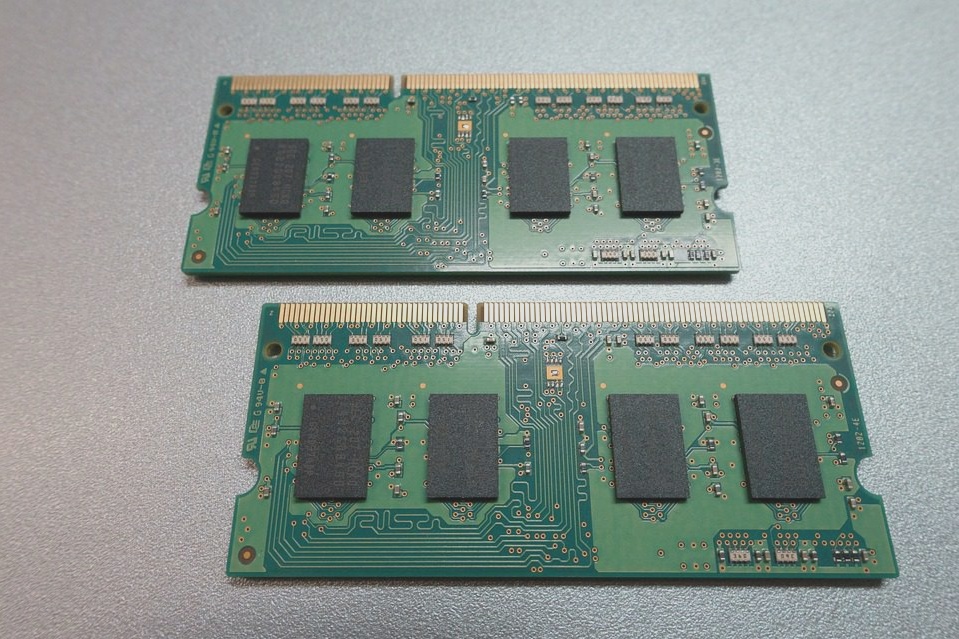
In PCB design, a 6-layer board should be considered for applications with higher chip density and clock frequency, and the following stacking methods are recommended:
1. SIG-GND-SIG-PWR-GND-SIG: This configuration offers improved signal integrity, as signal layers are adjacent to ground layers. The power and ground layers are paired, allowing for better control over the trace impedance. Both ground layers effectively absorb magnetic field lines, providing a superior return path for each signal layer when the power and ground layers are intact.
2. GND-SIG-GND-PWR-SIG-GND: This layout is suitable for situations with lower device density. It retains all the advantages of the first scheme, with a more complete ground plane on the top and bottom layers, serving as an effective shielding layer. It’s important to position the power layer close to a non-component surface, as the bottom plane will be more complete, resulting in improved EMI performance compared to the first solution.
Summary: In PCB layout and design, for the six-layer configuration, minimizing the distance between the power and ground layers is crucial for effective power and ground coupling. However, even with a board thickness of 62 mil and reduced layer spacing, achieving a small distance between the main power supply and ground layer can be challenging. While the second scheme increases costs significantly compared to the first, we typically opt for the first option when stacking. Additionally, it is essential to adhere to the 20H rule and the mirror layer rule during the design process.

### Stacking of Four and Eight-Layer Boards
1. This lamination method is not optimal due to poor electromagnetic absorption and high power supply impedance. Its structure includes:
1. Signal 1 component surface, microstrip wiring layer
2. Signal 2 internal microstrip wiring layer, superior wiring layer (X direction)
3. Ground
4. Signal 3 stripline routing layer, superior routing layer (Y direction)
5. Signal 4 stripline routing layer
6. Power
7. Signal 5 internal microstrip wiring layer
8. Signal 6 microstrip trace layer
2. This is a variation of the third stacking method. With the inclusion of a reference layer, it demonstrates improved EMI performance, allowing for better control over the characteristic impedance of each signal layer.
1. Signal 1 component surface, microstrip wiring layer, superior wiring layer
2. Ground layer, effective electromagnetic wave absorption
3. Signal 2 stripline routing layer, superior routing layer
4. Power layer, achieving excellent electromagnetic absorption with the ground layer beneath
5. Ground layer
6. Signal 3 stripline wiring layer, superior wiring layer
7. Power stratum, characterized by high power supply impedance
8. Signal 4 microstrip wiring layer, superior wiring layer
3. This is the optimal stacking method, as it utilizes multiple ground reference planes, resulting in excellent geomagnetic absorption capacity.
1. Signal 1 component surface, microstrip wiring layer, superior wiring layer
2. Ground layer, effective electromagnetic wave absorption
3. Signal 2 stripline routing layer, superior routing layer
4. Power layer, achieving excellent electromagnetic absorption with the ground layer beneath
5. Ground layer
6. Signal 3 stripline wiring layer, superior wiring layer
7. Ground stratum, enhanced electromagnetic wave absorption capacity
8. Signal 4 microstrip wiring layer, superior wiring layer
Choosing the number of layers for the design and how to stack them depends on various factors, including the number of signal networks on the board, device density, pin density, signal frequency, and board size. All these factors must be considered comprehensively. As the number of signal networks, device density, pin density, and signal frequency increase, it is advisable to opt for multilayer PCB designs. To achieve optimal EMI performance, it’s best to ensure that each signal layer has its own dedicated reference layer.
If you have any PCB manufacturing needs, please do not hesitate to contact me.Contact me