Advantages of SMT Technology in PCB Assembly
- Components can be mounted on both sides of the PCB, enabling high-density assembly.
- Precise placement of even the smallest components results in high-quality PCB assemblies.
Challenges with Component Adhesion in PCB Assembly
In certain situations, the adhesion of components to the PCB can be compromised, affecting assembly quality.
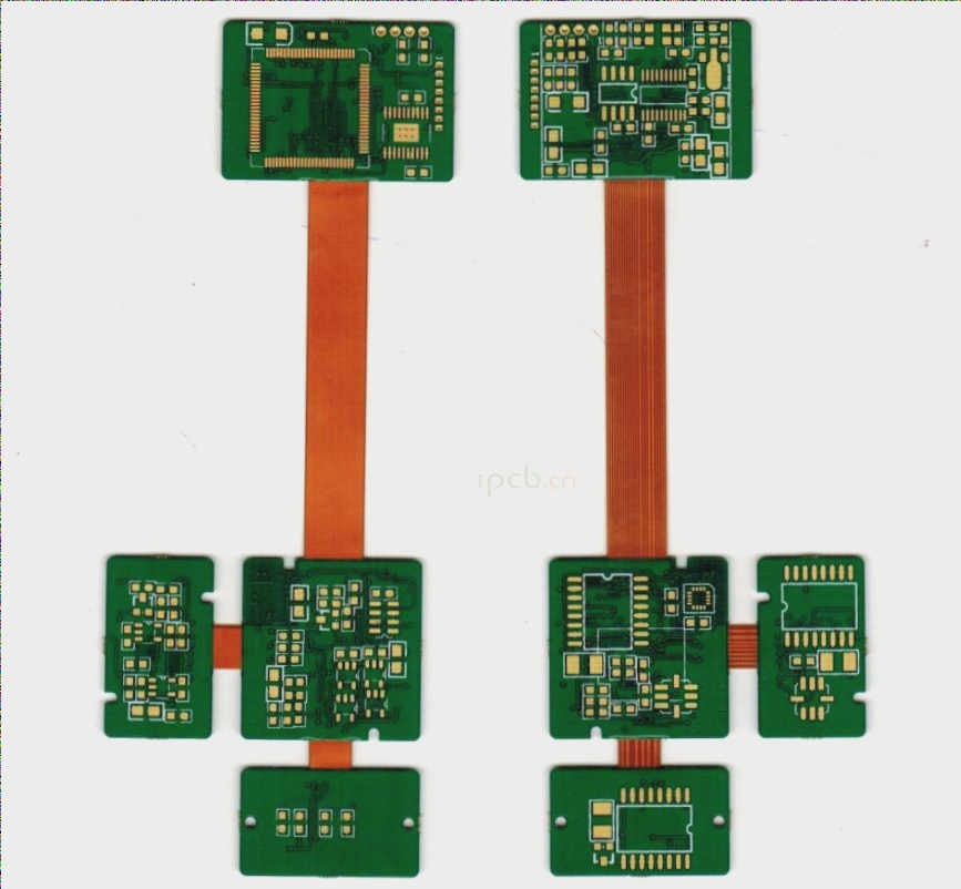
Comparison of SMT Components and Through-Hole Connectors
SMT components offer compact design and ease of mounting, differing significantly from through-hole connectors.
Considerations for Industrial Connectors
- High-power components used in industrial applications require adequate electrical clearance and creepage distance.
- Mechanical strength and ease of installation are crucial for connector reliability.
Cost Analysis of SMT and Through-Hole Components
SMT components account for 80% of components but only 60% of production costs, while through-hole components make up 20% of components but contribute to 40% of production costs.
Integrating Through-Hole Technology with SMT
Through-Hole Reflow (THR) process allows simultaneous assembly of through-hole and SMT components, enhancing efficiency.
Key steps for completing the THR process:
- Confirming compatibility of through-hole connectors with THR process.
- Adapting PCB design to new process requirements, including aperture size and pad ring design.
- Ensuring high-quality solder joints through proper evaluation and inspection.
Characteristics of Connector Components Suitable for THR
Steps to Complete the THR Process
1. Confirm Whether the Through-Hole Connector Can Adopt the THR Process
2. PCB Design Adaptation to New Process Requirements:
- Aperture Size: Selecting the appropriate size for optimal solder flow and assembly.
- Pad Ring Design: Recommended width for efficient solder joint evaluation.
THR technology offers a reliable solution for integrating through-hole and SMT components, enhancing PCB assembly efficiency.
PCB Solder Paste Application Techniques
The standard stencil thickness for PCB solder paste application ranges from 120μm to 150μm. It is important to avoid excessive coating pressure during the application process.
Formula for Proper Contact
To ensure proper contact between the pad ring and the template, while applying sufficient pressure to the solder paste without the need for frequent stencil cleaning, the following formula can be used:
[ ds = di + 2R – 0.1 ]
Here, (di) represents the aperture, and (R) denotes the pad ring width.
Quality of Solder Paste
During the coating process, the solder paste should exhibit good fluidity, wettability, and adhesion. This ensures that the paste flows into the holes and adheres well to the pins.
Applying Solder Paste to PCB Pads
When applying solder paste to PCB pads, it is essential to maintain the ideal coating pressure, as shown in Figure 7. The amount of solder paste applied to each pad should be twice the volume of the corresponding hole.
Adjusting the printing speed and squeegee angle can help achieve the required solder paste volume. For instance, modifying the squeegee angle can increase the pressure on the paste, as illustrated in Figure 8 (assuming a constant speed).
Another effective method is the closed coating system, which applies pressure directly to the solder paste, allowing for precise control over the paste volume.
Optimal Packaging Form Selection
In SMT processing, “tape packaging” is commonly used, with THR connectors typically adhering to this standard. The tape width typically falls within the range of 32mm to 88mm.
While THR components are compatible with most standard feeders, certain components, particularly vertical ones, may require verification of the feeder’s radius to ensure a proper fit at the feed and discharge points.
Various packaging forms, such as waffle trays or tubes, are supported by many machines, catering to diverse requirements, including dedicated or “unfinished” components.
Quality Check According to Standards
THR connectors can be inspected in accordance with the IPC-A-610C standard. Evaluation of the solder joints on the soldering surface is possible as long as the pins extend from the PCB.
Reducing Production Costs with THR Technology
When considering the adoption of THR technology, striking a balance between low production costs and higher component costs is crucial. THR connectors generally incur higher costs than standard components due to increased material and packaging expenses.
Several factors influence cost reduction potential, including the level of production automation, order volume, the possibility of replacing other through-hole components, and the need for new product designs or redesigns.
While not all manufacturers recommend THR connectors, opting for THR technology for the connector when all components except the PCB connector are processed through SMT can offer significant benefits in terms of cost and efficiency.
If you have any PCB manufacturing needs, feel free to contact me.