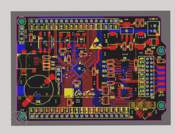
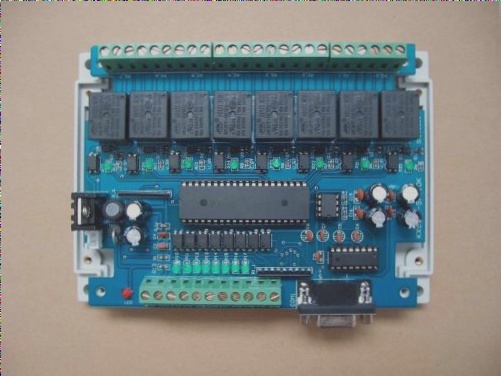
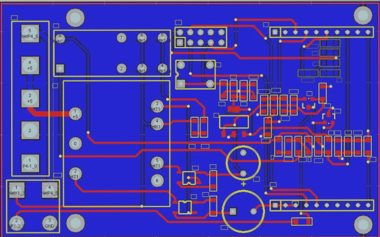
1. Conventional SMD Placement
Features: The placement accuracy is relatively low, the number of components is limited, and the primary component types are resistors and capacitors, along with a few specialized components.
**Key Process:**
1. **Solder Paste Printing:** The FPC is positioned on a specialized printing pallet based on its appearance. Typically, a small semi-automatic printing machine is used for this process, though manual printing is also an option; however, the quality of manual printing tends to be inferior to that of semi-automatic methods.
2. **Placement:** Manual placement is generally employed, while components that require higher positional accuracy can be placed using a manual placement machine.
3. **Welding:** The reflow soldering process is commonly used, though spot welding may be utilized in specific situations.
—
**High-Precision Placement**
**Features:** It is essential for the FPC to have a MARK indicator for substrate positioning, and the FPC itself must remain flat. Fixing the FPC can be challenging, making it difficult to maintain consistency during mass production, which raises the equipment requirements. Furthermore, controlling the solder paste printing and placement process is complex.
**The Key Process:**
1. **FPC Fixation:** From the solder paste printing to the reflow soldering, the entire process requires fixation on the pallet. The pallet must have a low thermal expansion coefficient. Two fixation methods are employed based on the QFP lead spacing: Method A is used when the lead spacing exceeds 0.65 mm, while Method B is used for lead spacings less than 0.65 mm.
– **Method A:** The pallet is positioned on a locating template. The FPC is secured to the pallet with a thin, high-temperature-resistant tape, which is then separated from the template for printing. This tape should have moderate adhesion, be easy to remove post-reflow soldering, and leave no residual adhesive on the FPC.
– **Method B:** A customized pallet is utilized, designed to minimize deformation after multiple thermal shocks. This pallet features a T-shaped positioning pin, which is slightly taller than the FPC.
2. **Solder Paste Printing:** With the FPC loaded onto the pallet and secured with high-temperature-resistant tape, there may be height discrepancies compared to the pallet plane, necessitating the use of an elastic scraper during printing. The composition of the solder paste significantly influences the printing outcome, so selecting the appropriate solder paste is crucial. Additionally, the printing template for Method B requires special processing.
3. **Mounting Equipment:** First, the solder paste printing machine must incorporate an optical positioning system, as the absence of such a system can severely affect welding quality. Second, while the FPC is fixed on the pallet, tiny gaps may exist between the FPC and the pallet, which distinguishes it from standard PCB substrates. Thus, the configuration of equipment parameters has a substantial impact on printing quality, placement accuracy, and welding effectiveness. Therefore, the placement of FPCs demands stringent process control.
—
Feel free to reach out if you need any further adjustments!

