1. **Function and Characteristics of Nickel Plating on Multilayer PCBs**
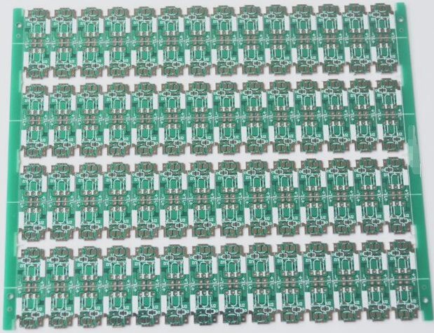
Nickel plating serves as a substrate coating for both precious and base metals on multilayer PCBs and is also commonly used as the surface layer for some single-sided PCBs. For surfaces subjected to heavy wear, such as switch contacts or plug-in contacts, nickel is applied as a base coating for gold, significantly enhancing wear resistance. As a barrier layer, nickel effectively prevents diffusion between copper and other metals. The nickel/gold composite coating is frequently used as an anti-etching metal layer, meeting the requirements for hot press welding and brazing. Nickel alone can be used as an anti-corrosion coating in environments with ammonia etchants, without requiring hot press welding. For multilayer PCBs with a bright finish, a light nickel/gold coating is typically used. The thickness of the nickel coating is generally not less than 2.5 microns, and is usually between 4-5 microns.
The low-stress nickel deposition layer on multilayer PCBs is commonly plated with modified Watt nickel plating solutions or certain sulfamic acid nickel plating solutions containing stress-reducing additives. Nickel plating on multilayer PCBs is characterized by smooth and dull nickel (also known as low-stress nickel or semi-bright nickel). The coating should be uniform, fine, low in porosity, low in stress, and exhibit good ductility.
2. **Nickel Sulfamate (Ammonia Nickel)**
Nickel sulfamate is widely used as a substrate coating for metallized hole electroplating and printed plug contacts. It offers low internal stress, high hardness, and excellent ductility. When a stress-relieving agent is added to the bath, the resulting coating will exhibit slight stress. Various formulations of sulfamate plating solutions exist, with a typical formulation shown in the table below. Despite its low-stress characteristics and widespread use, nickel sulfamate has poor stability and relatively high cost.
3. **Modified Watt Nickel (Sulfur Nickel)**
The modified Watt nickel formula uses nickel sulfate in combination with nickel bromide or nickel chloride. Nickel bromide is predominantly used due to its lower internal stress. This formulation produces a semi-bright coating with minimal internal stress and good ductility. Furthermore, this coating is easily activated for subsequent electroplating processes and is relatively cost-effective.

4. Function of Each Component of Plating Solution:
1. **Main Salts**: Nickel sulfamate and nickel sulfate are the principal salts in the nickel plating solution. Nickel salts primarily provide the nickel metal ions necessary for plating and also serve as conductive salts. The concentration of nickel salts in the solution can vary slightly among different suppliers, and the permissible content of nickel salts can differ significantly. A higher nickel salt content allows for high cathode current density and faster deposition rates, commonly used for high-speed thick nickel plating. However, excessively high concentrations can reduce cathodic polarization, decrease dispersion ability, and increase the loss of the plating solution. Lower nickel salt content leads to slower deposition but offers better dispersion and results in a fine, bright crystalline coating.
2. **Buffer**: Boric acid acts as a buffer to maintain the pH of the nickel plating solution within a specific range. Practical experience shows that a pH that is too low reduces cathode current efficiency, while a pH that is too high leads to the rapid increase of pH near the cathode surface due to continuous hydrogen gas precipitation, forming Ni(OH)₂ colloid. This inclusion increases the coating’s brittleness and retains hydrogen bubbles, increasing coating porosity. Boric acid not only stabilizes pH but also improves cathodic polarization, enhancing bath performance and reducing “coking” at high current densities. Additionally, boric acid helps improve the mechanical properties of the coating.
3. **Anode Activator**: In processes using sulfate nickel plating solutions, insoluble anodes are employed, while soluble anodes are used in other types of nickel plating. Nickel anodes tend to passivate during operation, so a certain amount of anode activator is added to the plating solution to ensure proper anode dissolution. Chloride ions (Cl⁻) are the most effective activators for nickel anodes. In solutions containing nickel chloride, nickel chloride acts both as a main salt and an anode activator. In solutions lacking or with low levels of nickel chloride, sodium chloride should be added as needed. Nickel bromide or nickel chloride can also serve as stress relief agents to control internal stress in the coating and achieve a semi-bright appearance.
4. **Additive**: The primary component of additives is stress relief agents. These agents improve cathodic polarization and reduce internal stress in the coating. By varying the concentration of stress relief agents, the coating’s internal stress can shift from tensile to compressive. Common additives include naphthalene sulfonic acid, p-toluenesulfonamide, and saccharin. Additives help produce a uniform, fine, and semi-bright coating compared to nickel coatings without such agents. Typically, stress relief agents are added based on amperage per hour, and special combinations of additives may include pinhole inhibitors.
5. **Wetting Agent**: During electroplating, hydrogen precipitation on the cathode is inevitable. This can reduce cathode current efficiency and cause pinholes in the coating due to trapped hydrogen bubbles. To mitigate this, a small amount of wetting agents, such as sodium dodecyl sulfate, sodium diethylhexyl sulfate, or sodium octyl sulfate, should be added. These anionic surfactants adsorb on the cathode surface, reducing the interfacial tension between the electrode and the solution, and lowering the wetting contact angle of hydrogen bubbles, facilitating their escape and reducing or preventing pinhole formation.
5. Maintenance of Plating Solution:
1. **Temperature**: Different nickel processes require specific bath temperatures. Temperature changes affect the nickel plating process in complex ways. At higher temperatures, the nickel coating exhibits lower internal stress and better ductility. Stability is reached around 50°C, with operational temperatures typically maintained at 55-60°C. If the temperature exceeds this range, nickel salt hydrolysis can occur, forming nickel hydroxide colloid that traps hydrogen bubbles, leading to pinholes and reduced cathodic polarization. Therefore, precise temperature control within the recommended range is crucial. A standard temperature controller should be used to maintain the optimal temperature as advised by the supplier.
2. **pH Value**: The pH of the nickel plating electrolyte significantly impacts coating and electrolyte properties. In strongly acidic solutions (pH ≤ 2), metal nickel does not deposit, and only light gas is evolved. For multilayer PCBs, the pH is generally maintained between 3-4. Higher pH values improve dispersion force and cathode current efficiency, but excessively high pH can lead to rapid formation of nickel oxide colloid, causing pinholes and increased coating brittleness. Lower pH values enhance anodic dissolution, allowing higher nickel salt content and current density but can narrow the temperature range for obtaining a bright coating. To adjust pH, add nickel carbonate or basic nickel carbonate to raise it, or sulfamic or sulfuric acid to lower it. The pH should be checked and adjusted every four hours during operation.
3. **Anode**: Conventional multilayer PCB nickel plating uses soluble anodes, often installed in titanium baskets to hold nickel anodes. This setup allows for a large anode area and simplifies maintenance. The titanium basket should be placed in an anode bag made of polypropylene to prevent anode mud from contaminating the plating solution. Regular cleaning and checking of the anode bag for blockages are necessary. New anode bags should be soaked in boiling water before use.
4. **Purification**: To address organic contamination in the plating solution, activated carbon treatment is used. This method may also remove some stress relief agents, necessitating supplementation. The purification process includes:
(1) Remove the anode, add impurity removal water (5 ml/L), heat to 60-80°C, and air pump (air stirring) for 2 hours.
(2) For significant organic impurities, add 3-5 ml/L of 30% hydrogen peroxide and stir with air for 3 hours.
(3) Add 3-5 g/L of powdered activated carbon while stirring continuously for 2 hours, then let it stand for 4 hours. Add filter aid powder, use a standby tank to filter, and clean the cylinder simultaneously.
(4) Clean and maintain the anode. Use a corrugated iron plate plated with nickel as the cathode, and drag the cylinder at a current density of 0.5-0.1 A/dm² for 8-12 hours. This step is also used when inorganic pollution affects plating quality.
(5) Replace the filter element periodically, using a series of cotton and carbon cores for continuous filtration. This helps delay extensive treatment and improve solution stability. Analyze and adjust parameters, and add wetting agents for test plating.
5. **Analysis**: Regularly analyze the plating solution using key process specifications and Hull cell tests. Guide the production department in adjusting plating solution parameters based on the obtained results.
6. **Stirring**: Stirring is crucial for accelerating mass transfer, reducing concentration changes, and increasing the allowable current density. Effective stirring also reduces or prevents pinholes in the nickel plating. Increased hydrogen precipitation near the cathode surface raises pH and forms nickel hydroxide colloid, leading to pinholes. This issue can be mitigated by intensifying stirring. Common methods include using compressed air, cathode movement, and forced circulation, often combined with carbon and cotton core filtration.
7. **Cathode Current Density**: The cathode current density impacts cathode current efficiency, deposition rate, and coating quality. Research shows that in low pH electrolyte regions, cathode current efficiency increases with current density. In high current density regions, efficiency is less affected by current density. For nickel electroplating, the cathode current density range should be tailored to the solution composition, temperature, and mixing conditions. For multilayer PCBs, the current density typically ranges from 2 A/dm², varying between high and low current areas.
6. Fault Causes and Troubleshooting:
1. **Hemp Pits**: Hemp pits result from organic contamination, with large pits indicating oil contamination. Poor mixing can trap bubbles, forming hemp pits. Using a wetting agent can reduce these effects. Small pits, often called pinholes, can result from poor pretreatment, insufficient boric acid, or low bath temperature. Proper bath maintenance and process control, including the use of pinhole inhibitors, are key.
2. **Rough Burr**: Roughness indicates dirty solutions, which can be corrected through full filtration. High pH may cause hydroxide precipitation, and high current density can introduce impurities from anode mud and make-up water, leading to roughness and burrs.
3. **Low Adhesion**: Poor copper oxidation or interrupted current can cause poor adhesion and peeling of the nickel coating. Low temperature can also affect adhesion.
4. **Brittle Coating**: Coating brittleness, often exposed when bent or worn, indicates organic or heavy metal contamination and excess additives. Organic matter pollution, sourced from entrained organic substances and electroplating resist, requires activated carbon treatment. Insufficient addition of stress relief agents and high pH can also affect coating brittleness.
5. **Darkening and Uneven Color**: Darkening and uneven color typically result from metal contamination, with copper solutions being a common source. Minimizing copper solution on hangers and using corrugated steel cathodes for metal removal at 2-5 A/sq. ft. current density can help. Poor pretreatment, low current density, low main salt concentration, and poor power circuit contact can also affect color.
6. **Coating Burn**: Causes of coating burn include insufficient boric acid, low metal salt concentration, low operating temperature, high current density, high pH, or inadequate mixing.
7. **Low Deposition Rate**: Low pH or current density can result in a reduced deposition rate.
8. **Blistering or Peeling**: Poor pret
Nickel plating serves as a substrate coating for both precious and base metals on multilayer PCBs and is also commonly used as the surface layer for some single-sided PCBs. For surfaces subjected to heavy wear, such as switch contacts or plug-in contacts, nickel is applied as a base coating for gold, significantly enhancing wear resistance. As a barrier layer, nickel effectively prevents diffusion between copper and other metals. The nickel/gold composite coating is frequently used as an anti-etching metal layer, meeting the requirements for hot press welding and brazing. Nickel alone can be used as an anti-corrosion coating in environments with ammonia etchants, without requiring hot press welding. For multilayer PCBs with a bright finish, a light nickel/gold coating is typically used. The thickness of the nickel coating is generally not less than 2.5 microns, and is usually between 4-5 microns.
The low-stress nickel deposition layer on multilayer PCBs is commonly plated with modified Watt nickel plating solutions or certain sulfamic acid nickel plating solutions containing stress-reducing additives. Nickel plating on multilayer PCBs is characterized by smooth and dull nickel (also known as low-stress nickel or semi-bright nickel). The coating should be uniform, fine, low in porosity, low in stress, and exhibit good ductility.
2. **Nickel Sulfamate (Ammonia Nickel)**
Nickel sulfamate is widely used as a substrate coating for metallized hole electroplating and printed plug contacts. It offers low internal stress, high hardness, and excellent ductility. When a stress-relieving agent is added to the bath, the resulting coating will exhibit slight stress. Various formulations of sulfamate plating solutions exist, with a typical formulation shown in the table below. Despite its low-stress characteristics and widespread use, nickel sulfamate has poor stability and relatively high cost.
3. **Modified Watt Nickel (Sulfur Nickel)**
The modified Watt nickel formula uses nickel sulfate in combination with nickel bromide or nickel chloride. Nickel bromide is predominantly used due to its lower internal stress. This formulation produces a semi-bright coating with minimal internal stress and good ductility. Furthermore, this coating is easily activated for subsequent electroplating processes and is relatively cost-effective.
4. Function of Each Component of Plating Solution:
1. **Main Salts**: Nickel sulfamate and nickel sulfate are the principal salts in the nickel plating solution. Nickel salts primarily provide the nickel metal ions necessary for plating and also serve as conductive salts. The concentration of nickel salts in the solution can vary slightly among different suppliers, and the permissible content of nickel salts can differ significantly. A higher nickel salt content allows for high cathode current density and faster deposition rates, commonly used for high-speed thick nickel plating. However, excessively high concentrations can reduce cathodic polarization, decrease dispersion ability, and increase the loss of the plating solution. Lower nickel salt content leads to slower deposition but offers better dispersion and results in a fine, bright crystalline coating.
2. **Buffer**: Boric acid acts as a buffer to maintain the pH of the nickel plating solution within a specific range. Practical experience shows that a pH that is too low reduces cathode current efficiency, while a pH that is too high leads to the rapid increase of pH near the cathode surface due to continuous hydrogen gas precipitation, forming Ni(OH)₂ colloid. This inclusion increases the coating’s brittleness and retains hydrogen bubbles, increasing coating porosity. Boric acid not only stabilizes pH but also improves cathodic polarization, enhancing bath performance and reducing “coking” at high current densities. Additionally, boric acid helps improve the mechanical properties of the coating.
3. **Anode Activator**: In processes using sulfate nickel plating solutions, insoluble anodes are employed, while soluble anodes are used in other types of nickel plating. Nickel anodes tend to passivate during operation, so a certain amount of anode activator is added to the plating solution to ensure proper anode dissolution. Chloride ions (Cl⁻) are the most effective activators for nickel anodes. In solutions containing nickel chloride, nickel chloride acts both as a main salt and an anode activator. In solutions lacking or with low levels of nickel chloride, sodium chloride should be added as needed. Nickel bromide or nickel chloride can also serve as stress relief agents to control internal stress in the coating and achieve a semi-bright appearance.
4. **Additive**: The primary component of additives is stress relief agents. These agents improve cathodic polarization and reduce internal stress in the coating. By varying the concentration of stress relief agents, the coating’s internal stress can shift from tensile to compressive. Common additives include naphthalene sulfonic acid, p-toluenesulfonamide, and saccharin. Additives help produce a uniform, fine, and semi-bright coating compared to nickel coatings without such agents. Typically, stress relief agents are added based on amperage per hour, and special combinations of additives may include pinhole inhibitors.
5. **Wetting Agent**: During electroplating, hydrogen precipitation on the cathode is inevitable. This can reduce cathode current efficiency and cause pinholes in the coating due to trapped hydrogen bubbles. To mitigate this, a small amount of wetting agents, such as sodium dodecyl sulfate, sodium diethylhexyl sulfate, or sodium octyl sulfate, should be added. These anionic surfactants adsorb on the cathode surface, reducing the interfacial tension between the electrode and the solution, and lowering the wetting contact angle of hydrogen bubbles, facilitating their escape and reducing or preventing pinhole formation.
5. Maintenance of Plating Solution:
1. **Temperature**: Different nickel processes require specific bath temperatures. Temperature changes affect the nickel plating process in complex ways. At higher temperatures, the nickel coating exhibits lower internal stress and better ductility. Stability is reached around 50°C, with operational temperatures typically maintained at 55-60°C. If the temperature exceeds this range, nickel salt hydrolysis can occur, forming nickel hydroxide colloid that traps hydrogen bubbles, leading to pinholes and reduced cathodic polarization. Therefore, precise temperature control within the recommended range is crucial. A standard temperature controller should be used to maintain the optimal temperature as advised by the supplier.
2. **pH Value**: The pH of the nickel plating electrolyte significantly impacts coating and electrolyte properties. In strongly acidic solutions (pH ≤ 2), metal nickel does not deposit, and only light gas is evolved. For multilayer PCBs, the pH is generally maintained between 3-4. Higher pH values improve dispersion force and cathode current efficiency, but excessively high pH can lead to rapid formation of nickel oxide colloid, causing pinholes and increased coating brittleness. Lower pH values enhance anodic dissolution, allowing higher nickel salt content and current density but can narrow the temperature range for obtaining a bright coating. To adjust pH, add nickel carbonate or basic nickel carbonate to raise it, or sulfamic or sulfuric acid to lower it. The pH should be checked and adjusted every four hours during operation.
3. **Anode**: Conventional multilayer PCB nickel plating uses soluble anodes, often installed in titanium baskets to hold nickel anodes. This setup allows for a large anode area and simplifies maintenance. The titanium basket should be placed in an anode bag made of polypropylene to prevent anode mud from contaminating the plating solution. Regular cleaning and checking of the anode bag for blockages are necessary. New anode bags should be soaked in boiling water before use.
4. **Purification**: To address organic contamination in the plating solution, activated carbon treatment is used. This method may also remove some stress relief agents, necessitating supplementation. The purification process includes:
(1) Remove the anode, add impurity removal water (5 ml/L), heat to 60-80°C, and air pump (air stirring) for 2 hours.
(2) For significant organic impurities, add 3-5 ml/L of 30% hydrogen peroxide and stir with air for 3 hours.
(3) Add 3-5 g/L of powdered activated carbon while stirring continuously for 2 hours, then let it stand for 4 hours. Add filter aid powder, use a standby tank to filter, and clean the cylinder simultaneously.
(4) Clean and maintain the anode. Use a corrugated iron plate plated with nickel as the cathode, and drag the cylinder at a current density of 0.5-0.1 A/dm² for 8-12 hours. This step is also used when inorganic pollution affects plating quality.
(5) Replace the filter element periodically, using a series of cotton and carbon cores for continuous filtration. This helps delay extensive treatment and improve solution stability. Analyze and adjust parameters, and add wetting agents for test plating.
5. **Analysis**: Regularly analyze the plating solution using key process specifications and Hull cell tests. Guide the production department in adjusting plating solution parameters based on the obtained results.
6. **Stirring**: Stirring is crucial for accelerating mass transfer, reducing concentration changes, and increasing the allowable current density. Effective stirring also reduces or prevents pinholes in the nickel plating. Increased hydrogen precipitation near the cathode surface raises pH and forms nickel hydroxide colloid, leading to pinholes. This issue can be mitigated by intensifying stirring. Common methods include using compressed air, cathode movement, and forced circulation, often combined with carbon and cotton core filtration.
7. **Cathode Current Density**: The cathode current density impacts cathode current efficiency, deposition rate, and coating quality. Research shows that in low pH electrolyte regions, cathode current efficiency increases with current density. In high current density regions, efficiency is less affected by current density. For nickel electroplating, the cathode current density range should be tailored to the solution composition, temperature, and mixing conditions. For multilayer PCBs, the current density typically ranges from 2 A/dm², varying between high and low current areas.
6. Fault Causes and Troubleshooting:
1. **Hemp Pits**: Hemp pits result from organic contamination, with large pits indicating oil contamination. Poor mixing can trap bubbles, forming hemp pits. Using a wetting agent can reduce these effects. Small pits, often called pinholes, can result from poor pretreatment, insufficient boric acid, or low bath temperature. Proper bath maintenance and process control, including the use of pinhole inhibitors, are key.
2. **Rough Burr**: Roughness indicates dirty solutions, which can be corrected through full filtration. High pH may cause hydroxide precipitation, and high current density can introduce impurities from anode mud and make-up water, leading to roughness and burrs.
3. **Low Adhesion**: Poor copper oxidation or interrupted current can cause poor adhesion and peeling of the nickel coating. Low temperature can also affect adhesion.
4. **Brittle Coating**: Coating brittleness, often exposed when bent or worn, indicates organic or heavy metal contamination and excess additives. Organic matter pollution, sourced from entrained organic substances and electroplating resist, requires activated carbon treatment. Insufficient addition of stress relief agents and high pH can also affect coating brittleness.
5. **Darkening and Uneven Color**: Darkening and uneven color typically result from metal contamination, with copper solutions being a common source. Minimizing copper solution on hangers and using corrugated steel cathodes for metal removal at 2-5 A/sq. ft. current density can help. Poor pretreatment, low current density, low main salt concentration, and poor power circuit contact can also affect color.
6. **Coating Burn**: Causes of coating burn include insufficient boric acid, low metal salt concentration, low operating temperature, high current density, high pH, or inadequate mixing.
7. **Low Deposition Rate**: Low pH or current density can result in a reduced deposition rate.
8. **Blistering or Peeling**: Poor pret

