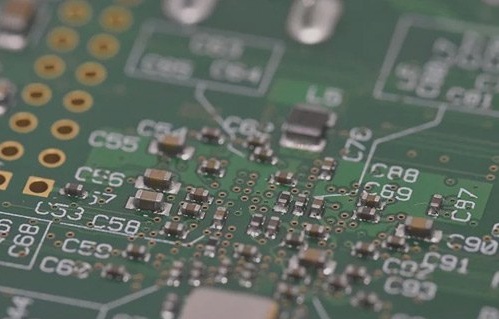
Understanding Circuit Board Faults in Electrical Testing
- When conducting electrical tests on circuit boards, faults are deviations from expected measurements indicating a good board.
- Guidelines are beneficial when specific directions are lacking, with shorts and opens in circuits causing significant issues.
- Not all faults can be detected by an electrical test system, and the definition of “all faults” is subjective.
- The system may not identify faults related to aesthetics, annular rings, or layer-to-layer registration unless they have a measurable effect.
- Effectiveness of electrical testing varies based on factors like measurement type, test fixture, program generation method, and end-user requirements.
- It’s crucial to differentiate between a defect and a fault in the context of circuit board testing.
- A fault is an item that doesn’t meet expected criteria, while a defect refers to issues with the board itself.
- Some defects may not be detectable by the test system.
Types of Circuit Board Faults:
Shorts, hard shorts, or short circuits are low-resistance connections between networks, often caused by various factors like exposure problems or under-etching.
Opens result in missing connections within a circuit network and can be caused by over-etching or layer registration errors.
Microvias in substrates can develop latent defects post-testing, necessitating careful ohmic measurements to prevent future open circuits.
Importance of RF Characteristics in Circuit Boards:
Modern circuits, including microprocessors and RF amplifiers, require specific RF characteristics in interconnections between components on printed wiring boards.
RF transmission line impedance, influenced by materials, trace dimensions, and proximity to ground planes, is a crucial parameter for maintaining circuit performance.


Understanding RF Impedance Measurement with Time Domain Reflectometry (TDR)
Time Domain Reflectometry (TDR) is a popular method for assessing RF impedance in PCBs. TDR measurements offer insights into the RF impedance profile along the trace length. It’s important to note that distance and time are closely linked in this context, as electrical signals travel through the board at speeds close to that of light.
Typically, TDR testing is carried out on a test coupon that is attached during the manufacturing process and later removed. While testing on actual product traces is also possible, it requires uninterrupted trace lengths of several inches without any branches or other configurations. The RF impedance values on circuit boards usually range from tens of ohms to several hundred ohms.

RF Impedance vs. DC Resistance
It’s essential to distinguish RF impedance from ordinary DC resistance. Unlike common ohmmeters used for measuring resistance, RF impedance cannot be accurately assessed using these devices, even though both use ohms as the unit of measure. The RF characteristics of interconnections are typically analyzed in the frequency domain with instruments called network analyzers, although this method is not commonly employed in bare board testing. The demand for RF impedance testing grows as signal frequencies exceed 100 MHz.


