PCB Radar in Automotive Applications
Introduction to PCB Radar
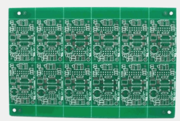
A PCB radar plays a vital role in generating, transmitting, and receiving radio frequency signals. It typically comprises an antenna structure and a radio frequency circuit mounted on high-frequency laminated materials.
Antenna Structure and Radio Frequency Circuit
- The antenna structure transmits radio frequency signals from the circuits and receives reflected signals after interacting with objects.
- The radio frequency circuit generates, receives, and analyzes radio frequency signals, emphasizing the importance of precision for stability and reliability.

Application of PCB Radar in Automobiles
Printed circuit boards (PCBs) are essential components widely used in various electronic devices, including automobiles. They offer mechanical support for electrical components like transistors, capacitors, and resistors, enabling wiring and electrical connections.
Role of Radar Systems in Vehicles
- Radar systems enhance automotive safety performance, with radar being a key technology in modern vehicle safety systems.
- Car radar aids in adaptive cruise control, collision avoidance, blind spot detection, and other safety features.
Millimeter Wave Radar PCB Boards
Millimeter wave radar PCB boards, a new electronic component, measure distance, velocity, and direction using millimeter waves’ reflection principle.
Design and Manufacturing Challenges
Designing and manufacturing millimeter wave radar PCB boards involve considerations like millimeter wave transmission, circuit design, and ultrasonic electronics, the core component controlling wave transmission and reception.
Future Trends in Unmanned Vehicles
Unmanned vehicles integrate sensors like millimeter wave radar, video cameras, LiDAR, and infrared detectors for heightened safety requirements.
Role of Radar Systems in Unmanned Vehicles
- The integration of sensors like millimeter wave radar enhances safety in unmanned vehicles.
- Radar systems detect dangerous road conditions, contributing to improved safety in various driving scenarios.
Automotive Millimeter Wave Radar
PCB radar reduces the number of printed circuit boards in radar modules, leading to miniaturization, high integration, and multifunctionality, optimizing system performance and cost-effectiveness.


