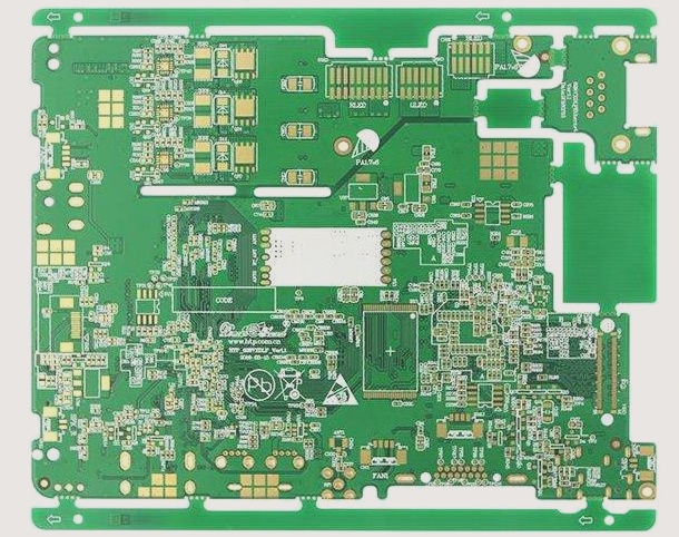
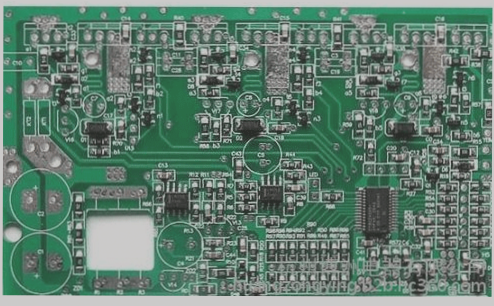
The following is an introduction to using a short-circuit tracker to detect PCB short-circuit faults:
1. The first scenario:
If the online functional test of U1 shows that pin 4 is not flipped and the test fails, switch to the pin status window in impedance display mode. Compare the impedance to ground between pin 4 of U1 and other output pins. If the impedance of each output pin is equal, it indicates internal damage to U1, necessitating replacement.
Measure the impedance between pin 4 of U1 and ground. If the logic state of this pin is low, its impedance will be relatively high (greater than 10 ohms); if the pin is at a high logic level, the impedance will exceed 1 kiloohm.
Use a multimeter to measure the resistance from pin 4 of U1 to ground. If it reads close to zero, employ a milliohm meter to precisely locate the short circuit using the “two-point positioning method” pioneered by Qtech. The QT25 and QT50 short-circuit trackers from Qtech are optimal tools for pinpointing short-circuit faults on PCBs.
2. The second scenario:
Steps for the “two-point positioning method”:
Begin by placing the milliohm meter probe on the solder joint of the measured pin, near its base (as depicted in the figure below). Set the milliohm meter range to 200 milliohms and record the resistance value. Next, move the probe to the adjacent copper trace, approximately 3-4 mm away from the solder joint of the tested pin (as shown in the figure below), and note the resistance value. If the first resistance value is lower than the second, it indicates that the short circuit point resides within the internal drive circuit of the chip under examination.
The chip should definitely be replaced at this point. If the resistance measured previously is higher than the current one, it indicates that the short circuit is not within the tested chip but could be on other connected chips or the copper traces on the PCB.
The short circuit resistance measured by the milliohmmeter varies with the severity of the short circuit. However, using the “two-point positioning method,” any difference between the resistances measured can pinpoint the actual short circuit location.
In the third scenario:
The actual fault on the PCB is that pin 5 of U3 is shorted to ground due to internal transistor breakdown at the input pin. During the U1 function test, failure occurs because pin 4 cannot switch correctly. Switch the fixture window to impedance display mode and compare pin 4’s impedance with other output pins. It is found that pin 4 has significantly lower impedance (close to zero). At this stage, uncertainty remains whether the fault lies with U1, necessitating further investigation using QT25 or QT50 short-circuit trackers. First, employ the “two-point positioning method” to ascertain if the short circuit is within or outside U1. Upon determining it’s outside U1, trace all chips connected to U1’s pin 4 using the board’s circuit diagram or Qtech’s line tracking feature. Use a short-circuit tracker to measure ground resistance on these pins and find that pin 5 of U3 has the lowest resistance to ground. The possibility of a short circuit between U1 and U2 is ruled out, focusing the issue on U3’s pin 5. Reapply the “two-point positioning method” to confirm the short circuit is within U3’s pin 5. U3 should then be replaced.
However, testing U3 now might still pass due to the short circuit at pin 5 to ground having a resistance value above the tester’s minimum drive resistance threshold, and the logic functions inside U3 remain intact. For example, like the 7400 NAND gate, a shorted input pin to ground may still pass functional tests. Nonetheless, detecting the internal short circuit at U3’s pin 5 confirms U3 damage, as PCB designers do not intend to short a chip’s output pin to ground.
In the fourth scenario:
Pin 3 of U2 is partially shorted to ground, showing around 10 ohms resistance when measured with a multimeter.
It’s crucial for users to note: under normal circumstances, resistance between input and output pins of a functioning chip to ground should not fall between 10-40 ohms.
During PCB testing of U1, failure occurs (as pin 4 of U1 cannot drive such a low-resistance input pin), with the screen indicating pin 4 is in a low-resistance state. Measuring pin 4’s resistance to ground also shows about 10 ohms. Standard milliohmmeters are inadequate to pinpoint the exact location of this incomplete short circuit due to the 10 ohm resistance measurement. To resolve this, the QT50 short-circuit tracker adjusts the measurement zero position to effectively mask fixed resistances of 10-20 ohms. Operationally, set the measurement zero to 10 ohms and the range to 200 milliohms, then proceed with measurements as outlined in the third scenario above.