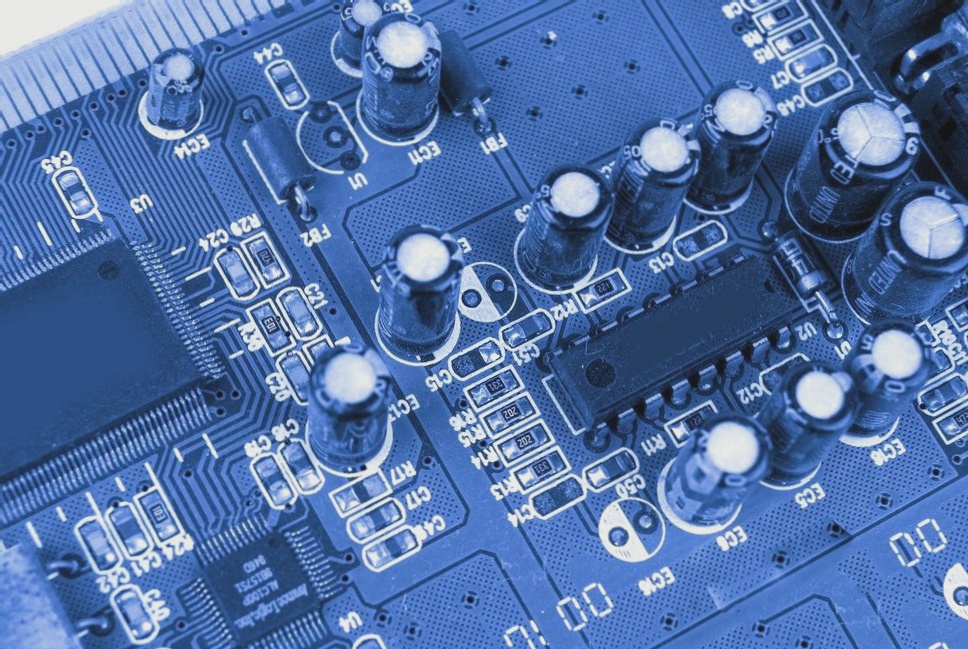
Benefits of Using Connectors for Printed Circuit Boards
- Enhanced modifiability, recovery time, and scalability for electronic product design.
- Speed up product assembly using ready-made modules based on PCBs.
Additional Details in Connector Manufacturing
- Coding elements to prevent SMD mounting errors.
- Fixing blocks for secure attachment to PCBs.
- Cases and cable clamps for easy cable splicing.
- Light tubes for voltage signaling at contact ends.
Functions of PCB Connectors
- Reliable and safe cable connections for various applications.
- Modular automation system for industrial, process, and power automation.
- Extensive range of input and output modules for diverse applications.
Various Variants and Applications of PCB Connectors and Multi-Plugs
- Wide range of connectors for different applications.
Connectors for Printed Circuit Boards
- Multiple variants of PCB terminal blocks available.
- Options for different cable approach angles and conductor cross-sections.
- Freedom to choose cable assembly methods in connectors.
Connection Technology for Lighting Fixtures
- Specialized connectors for lighting technology applications.
- Designed for easy power supply connection with minimal interference.
- Various variants suitable for different lighting setups.
Multiple Plug System (MCS)
- Full range of multi-plugs for structured cabling solutions.
- Available in different product families for various applications.
- Specially developed MCS MAXI family for high-current applications.
Enhancing Electronic Systems with Electrical Connectors
In the realm of electronic and electrical systems, a diverse array of additional accessories serves to safeguard plugs from accidental disconnection, secure individual components to support structures, and organize the wiring connected to sockets and plugs efficiently.
Multi-Plugs with Advanced Connection Coding
Explore a comprehensive selection of connectors and multi-plugs tailored for electronics, accompanied by a wealth of knowledge, an online catalog, and downloadable publications at www.wago.pl.
Electrical connectors play a vital role in every electronic system, facilitating seamless communication and power distribution between interconnected elements. Understanding the basics of connector construction and classification is essential for system integration.

Exploring Electrical Connectors: Types and Construction
Electronic systems rely on connectors to establish connections between various elements, enabling effective communication and energy transfer within the system hierarchy.
Electrical connectors are categorized into three main types based on the elements they connect:
- Board-to-Board: linking multiple printed circuit boards together
- Board-to-Wire: connecting printed boards with electric wires
- Wire-to-Wire: interconnecting wires within the system
The hierarchy of connections in electronic systems comprises six levels, each serving a specific purpose:
- Level 0: Integrated circuit connection to housing pins
- Level 1: Connection between electronic component housing and PCB surface
- Level 2: Interconnection of multiple printed circuits
- Level 3: Component connections within a single system
- Level 4: Components linked to I/O ports of the entire system
- Level 5: Inter-system connections, e.g., computer to printer
Advantages of Board-to-Board Connectors
Board-to-board connectors facilitate direct connections between printed circuit boards without the need for additional wires, optimizing space utilization and reducing system weight.
These connectors allow for parallel or perpendicular board configurations, with “mezzanine” connectors enabling stacking or vertical connections. Considerations when selecting mezzanine elements include joint height, dimensional tolerances, and assembly compatibility.
Meeting System Requirements with PCB Connectors
System specifications play a crucial role in connector selection, determining factors like reusability, expected disconnect/reconnect cycles, and environmental conditions. Compliance with standards such as EIA 700AAAB ensures connector performance and reliability.
Backplane solutions are common in board-to-board connections, forming interconnected bus configurations ideal for telecommunications applications, offering flexibility, reliability, and support for various expansion cards.
Importance of Impedance Matching and Shielding in High Data Transfer Rates
When dealing with high data transfer rates, the backplane can cause signal attenuation, leading to decreased signal quality and connection performance. To combat this issue, it is crucial to ensure proper impedance matching of components within the system and to implement effective signal shielding.
Cable Connections: Wire-to-Wire
- Cable connections directly link two electrical conductors together, with one end permanently attached to the cable.
- Rigid connections can be achieved through crimping or using IDC (Insulation Displacement Contact) technology.
- In IDC connections, insulated wires are inserted into specially designed sockets with sharp metal elements that pierce the insulation, establishing a direct connection.
- IDC is commonly used for connecting cables in tape form, while crimp assembly is preferred for single conductors.
Board-to-Wire Connections
Board-to-cable connectors facilitate the connection between wires and printed circuit boards. These connectors typically feature wire-to-wire solutions on one end and push-in or solderable connectors on the board end.


