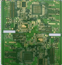
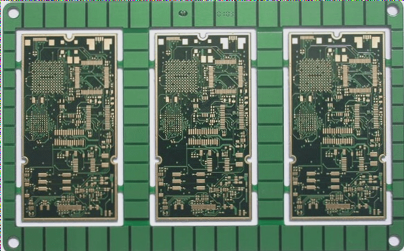
In the PCB circuit board production process, various defects can arise, such as poor copper wire adhesion, commonly referred to as copper rejection, which negatively impacts product quality. The common causes of copper rejection in PCB circuit boards are outlined below:
1. **Manufacturing Process Factors:**
1) Copper foil over-etching is a frequent issue. The electrolytic copper foils available on the market are typically single-sided galvanized (known as ashing foil) and single-sided copper plated (referred to as red foil). Standard copper foil usually exceeds 70µm in thickness. Foils that are red or ashing below 18µm rarely experience copper rejection.
2) Localized collisions during the PCB process can result in copper wire detachment from the substrate due to external mechanical forces. This issue often stems from poor positioning or alignment, leading to twisted copper wires or scratches/impact marks in the same direction. When inspecting the defective area by peeling back the copper wire, the rough surface of the copper foil will appear normal in color, with no signs of edge erosion, and the adhesion strength of the copper foil will be satisfactory.
3) Unreasonable PCB circuit designs can contribute to this issue, particularly when thick copper foil is used to create thin circuits, resulting in over-etching and subsequent copper loss.
2. **Laminate Manufacturing Process Reasons:**
Under normal circumstances, as long as the laminate is hot pressed for over 30 minutes, the copper foil and the prepreg will be effectively bonded together. Therefore, the pressing process generally does not compromise the adhesion between the copper foil and the substrate within the laminate. However, during the stacking and lamination of layers, if the prepreg becomes contaminated or if the matte surface of the copper foil is damaged, it can lead to inadequate bonding strength between the copper foil and the substrate post-lamination. This may result in positioning issues (primarily for large panels) or sporadic copper traces detaching, although the peel strength of the copper foil near the affected area remains normal.
3. Reasons for laminate raw materials:
1). Standard electrolytic copper foils are products that have been galvanized or copper-plated on a base foil. If the peak quality of the base foil is compromised during production, or if there are issues during the galvanizing/copper-plating process—such as poor plating crystal branching—this can lead to insufficient peel strength in the copper foil itself. Consequently, when defective foil is used to manufacture a PCB and inserted in an electronic assembly, external forces can cause the copper traces to detach. Notably, this type of poor copper adhesion will not typically result in obvious side corrosion after the copper wire is peeled back, revealing a rough surface on the contact side with the substrate. However, the overall peel strength of the copper foil will be significantly weakened.
2) Poor compatibility between copper foil and resin: Some laminates with specialized properties, such as high Tg (glass transition temperature) sheets, require different resin systems. Typically, these use PN resin as the curing agent, which features a simpler molecular chain structure and lower cross-linking density. It is crucial to pair these laminates with a specifically designed copper foil. If an incompatible copper foil is used during the lamination process, it can lead to inadequate peel strength of the metal-clad foil, resulting in poor copper trace retention during insertion.