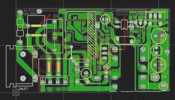
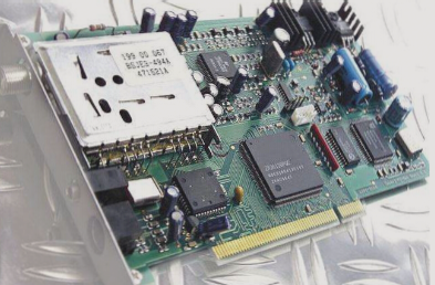
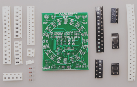
2. Typically, on a self-made PCB, components are installed after the tinning process is complete. However, if the board is made by someone else, it might only be a tinned PCB with drilled holes, requiring you to install the components yourself once you receive it.
3. Some designers are very familiar with the PCBs they create and prefer to test all components at once. However, it’s generally more effective to test each component individually as you progress.
4. When debugging a new PCB, it’s advisable to begin with the power supply section. The safest approach is to include a fuse in the design and then connect the power supply. For extra precaution, it’s recommended to use a regulated power supply.
1. **Use a stabilized power supply to set the overcurrent protection current, and then gradually increase the output voltage.** During this process, it’s important to monitor the input current, input voltage, and output voltage of the board.
2. **If the voltage is increased without triggering overcurrent protection, and the output voltage remains within normal range, it indicates that the power supply section of the board is functioning properly.** However, if the output voltage is abnormal or overcurrent protection is triggered, further investigation is required to identify the fault.
3. **Component Installation on the Circuit Board**
When debugging the circuit, install the modules one by one. After installing each module or group of modules, follow the above procedure to test the board. This approach helps identify early design flaws or installation errors that could potentially lead to overcurrent damage or faulty components.
4. **If a failure occurs during the installation process, the following methods can be used to troubleshoot:**
**Troubleshooting Method 1: Voltage Measurement**
When overcurrent protection is triggered, do not rush to remove components. First, check the power supply voltage at each chip’s pin to ensure it’s within the specified range. Then, verify the reference voltages, operating voltages, and other critical points.
For example, when a silicon transistor is turned on, the voltage at the base-emitter junction (BE) should be around 0.7V, while the collector-emitter junction (CE) should typically be 0.3V or lower.
If the BE junction voltage is found to be higher than 0.7V (excluding special transistors like Darlington pairs), this could indicate an open BE junction. Proceed by checking the voltages at each subsequent point to isolate the fault.
5. **Troubleshooting Method 2: Signal Injection**
Signal injection is more complex than voltage measurement. When injecting a signal into the input terminal, measure the waveform at various points to locate the fault based on waveform behavior.
Alternatively, you can use tweezers to probe the input terminal. Touch the terminal with the tweezers and observe the response. This method is particularly useful in audio and video amplifier circuits (note: do not use this method with high-voltage or hot circuits, as it may pose an electric shock hazard).
If the previous stage functions correctly and the subsequent stage responds, it suggests the fault lies in the previous stage, not the next.
6. **Troubleshooting Method 3: Other Techniques**
**PCB Visual Inspection**
The first two methods are straightforward and effective. However, other techniques, such as seeing, smelling, listening, and touching, also play a role. These techniques require experience to be used effectively.
– “Seeing” refers not only to observing the state of the testing equipment but also checking for physical damage to components.
– “Smelling” involves detecting unusual odors, such as burnt smells or the scent of leaked electrolytes, which can indicate component failure. Damaged components often emit a distinct burnt smell.
– “Listening” involves checking if the board operates silently or if abnormal sounds are heard under power.
– “Touching” refers to feeling the temperature of components to identify overheating. While components may feel warm, they should not be excessively hot. Do not touch components directly with bare hands to avoid burns from high temperatures.
1. Whether you are working with a PCB made by someone else or one you have designed and fabricated yourself, the first step is to verify the integrity of the board. This includes checking for issues such as proper tinning, cracks, short circuits, open circuits, and drilling accuracy. If the board has been manufactured with more precision, you can also measure the resistance between the power supply and ground as an additional check.


