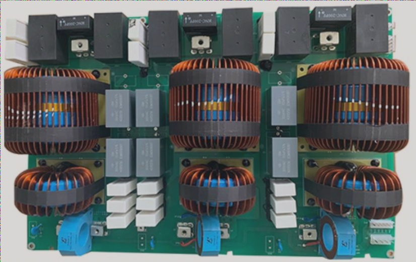
When we receive a circuit board for repair, the first step is to closely examine its surface. If the circuit board appears burnt, it’s crucial to thoroughly check the power circuit’s integrity before powering the board. This observation process is a static inspection method, typically following these steps.
The initial step is to assess whether the circuit board has sustained any physical damage, focusing on the following aspects.
First, examine if the circuit board has been dropped, which may cause deformations at the corners or breakage of components.
Next, inspect the chip sockets to see if specialized tools are necessary, as these are often required for proper handling.
Third, verify that the chip on the circuit board is correctly seated in the socket, as incorrect insertion by the operator can lead to misalignment. If not addressed promptly, this may result in chip damage and unnecessary losses when powering on the circuit board.
Finally, if there is a short terminal on the circuit board, ensure that it has not been incorrectly inserted.
Circuit board maintenance demands both theoretical knowledge and hands-on diligence, as careful observation by the technician is essential to accurately diagnose the issue.
**1.** The second step is to check for burnt components on the circuit board. For instance, resistor-capacitor diodes may appear blackened or burnt. Under normal circumstances, even if a resistor is damaged, its resistance will remain unchanged, and it won’t affect regular operation. In this case, you should use a multimeter for measurement. However, if a capacitor or diode is burnt, their performance will change within the circuit, preventing normal functionality and affecting the entire circuit’s operation. In such instances, it’s necessary to replace the damaged components.
**2.** The third step involves inspecting the integrated circuits on the circuit board, such as 74 series CPUs and other chips, for cracks or discoloration. If you observe these issues, it’s highly likely that the chip is damaged and requires replacement.
**3.** The fourth step is to examine whether the traces on the circuit board are peeling or burnt. Check if the deep copper vias have become detached from their pads.
**4.** Step 5: Look at the fuse (including fuse and thermal resistors) on the circuit board to determine if the fuse has melted. Sometimes, a fuse may be too thin to clearly assess, necessitating the use of a multimeter to confirm its status.
**5.** Most of these issues stem from excessive current flowing through the circuit. However, the specific cause of the overcurrent must be analyzed. The overall approach to troubleshooting begins with a careful examination of the circuit board’s schematic, gradually deriving the superior circuits based on the location of the burnt components. Leveraging accumulated experience, you can identify the most likely problem areas and ascertain the failure’s cause.
**6.** Before taking measurements, first determine whether the circuit operates on an analog or digital signal. For a circuit board with a schematic, you can assess this by reviewing the diagram. In cases where no schematic is available, there are typically two methods to ascertain whether the board contains a microprocessor. Whether it’s an early 8051 series or a widely-used DSP, the presence of such a chip indicates a bus structure on the board. Digital signals will dominate the processing, thus categorizing it as a digital board. Additionally, if many chips on the board operate at 5V, it is likely a digital circuit, as repairs will differ between digital and analog systems. Generally, analog circuits are easier to maintain, whereas digital circuits pose more challenges due to the bus structure lacking a clear hierarchy. The following focuses on the static measurement method for digital circuits, following these steps:
**7.** Step 1: Use a multimeter to check for short circuits between the power supply and ground. To perform this inspection, find a chip powered by 5V and measure two diagonal points (e.g., on a 14-pin chip, measure pins 7 and 14). For a 16-pin chip, measure pins 8 and 16. If no short circuit is detected between these points, the power supply is likely functioning correctly. If a short is present, further investigation is required.
**8.** These steps outline the basic concepts of power supply maintenance, especially for complex circuit boards, which may necessitate detailed analysis.
**9.** Step 2: Use a multimeter to measure diodes and verify their proper functionality. Typically, the resistance should read tens to hundreds of ohms. Diode failure usually occurs due to excessive current in the circuit.
**10.** Step 3: Measure the capacitance using the multimeter’s resistance setting to check for shorts. This step helps determine whether the issue lies with the component itself or the circuit it connects to, enabling a systematic problem identification.
**11.** Step 4: Measure the resistance of transistors on the circuit board to assess whether they meet logical performance criteria. If the circuit includes a bus structure, there will usually be a row of pull-up resistors on the bus. Resistance measurement is crucial, as it allows for a preliminary inspection of the chips attached to the bus.
**12.** Online measurement methods are typically employed by large PCB manufacturers to facilitate maintenance and establish a standardized debugging and maintenance platform. This approach easily provides the necessary power supply and initial signals for the circuit board. The primary goals of the online measurement method are twofold: first, to subdivide issues identified in the initial steps into specific components, and second, to address unresolved problems.
**13.** The online measurement process generally involves the following steps:
**14.** Step 1: Note that some circuit boards may require multiple power supplies, such as 5V, 12V, and 24V. Ensure that all necessary power supplies are connected. When powering the circuit board, check if any components in the 74 series chip are burnt. If damaged components are found, replace them and verify whether the circuit board fault has been resolved.
**15.** Step 2: Use an oscilloscope to measure the gate circuit on the circuit board and assess its logic levels. If the output appears illogical, two scenarios must be addressed: either the output should be low, in which case a high level reading would indicate chip damage, or the output should be high, requiring disconnection from the back circuit for further measurement to ascertain chip quality.
**16.** Step 3: Measure the crystal oscillators within the digital circuit using an oscilloscope to check for output. If no output is detected, remove the connected chip before re-measuring. Absence of output indicates that the crystal oscillator is likely damaged; if output is present, reinstall the chip and test further to locate the fault.
**17.** Step 4: Digital circuits with a bus structure usually include a digital address control bus. Measure the third line with an oscilloscope and compare it against the schematic to confirm whether the signal is normal.
**18.** The online measurement method primarily involves comparing functioning and non-functioning circuit boards to diagnose problems through comparative analysis. This approach effectively completes the maintenance of the circuit board.
**19.** This article elaborates on various methods and techniques in circuit board maintenance from three perspectives: observational methods, static measurement techniques, and dynamic measurement approaches. As technology advances, there is increasing focus on new instruments and equipment. Nonetheless, for those in electronic engineering, proficiency with basic testing tools such as multimeters and oscilloscopes remains a crucial skill.