1. There are numerous manifestations of high-speed PCB issues, such as overshoot, crosstalk, ringing, and more. To aid in classification and research, some leading simulation software vendors have made the following categorizations:
2. Common SI problems include reflection, crosstalk, overshoot, undershoot, monotonicity, etc.; solutions involve addressing driving issues, calculating termination resistance or series damping resistance, evaluating PCB stack-up structure and characteristic impedance, and analyzing routing topology.
3. At the end of the 20th century, companies like Huawei and ZTE introduced advanced simulation techniques from abroad and promoted them in China. Over the years, the industry has gained extensive experience with common SI problems. Attention shifted towards stack-up design, considering the impact of the reference plane; the concept and significance of impedance control became well understood, leading to strict impedance management in both design and manufacturing stages; there was also increased research into topology and termination matching methods, which can now be effectively applied in practical designs. It’s safe to say that the research and analysis of common SI issues have become relatively mature.
4. Timing: Timing remains a critical issue. Today’s designers primarily rely on ready-made solutions provided by core chip manufacturers. As a result, the primary focus of design is ensuring that the PCB meets the timing requirements of the chip.
The timing issue is relatively complex, and mainstream simulation software support for this area is somewhat limited (Sisoft has a dedicated timing analysis tool called Quantum-SI, though I have not personally used it). While most people have a basic understanding of timing, you can gain insight into the current state of timing design by looking at the various disorganized isometric requirements. In the following discussion, the author will focus on timing-related issues and provide an in-depth look at categories such as common clocks, source synchronous clocks, and internal synchronous clocks.
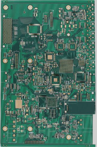
**Simulation challenges above MGH**: Transmission problems in the microwave frequency range are generally referred to as GHz simulation analysis. Designs need to address issues traditionally associated with the microwave field, such as the small dimensions of traces, vias, and materials on the transmission link.
This has also become a more popular area of “field” simulation in recent years, which spans a broader range of knowledge. Engineers working in this area are required to have expertise in “field” theory. At the same time, this has become a competitive space for software vendors. Along with the traditional industry standard HFSS, tools like ADS and CST dominate the 3D Full-Wave EM field. Sigrity, known for its Power SI tool, has also established itself in this space. Hyperlynx, having acquired the 3D modeling company Zealand IE3D last year, has also ventured into 3D field simulation. Only Cadence continues to pursue its own development path in 3D Full-Wave EM, claiming that a practical version will be released next year, but it will take time to gain recognition in the industry. MGH simulations are highly reliant on software. Unlike timing or general SI issues, which can often be analyzed manually through calculations, MGH simulations are more specialized, and will be covered in greater detail in a later discussion.
In addition to SI, PI (Power Integrity) has gained significant traction recently. As voltages continue to decrease and power consumption increases, PI has evolved beyond simply adding a few capacitors, which previously had little practical effect. More simulation engineers are now focusing on PI, and the co-simulation of PI and SI has become a hot topic in recent years. At DesignCon 2006, 2007, and in subsequent years, PI was one of the primary topics of discussion.
The main objectives of PI analysis include:
– Identifying “hot spots” of current and temperature;
– Guiding cascade design and plane segmentation;
– Optimizing capacitor selection and layout;
– Quickly determining the resonant frequency of the power distribution network;
– Guiding power supply design through time-domain simulations.
PI primarily addresses DC voltage drop issues, also known as IR-Drop. Simulation tools for this are relatively mature, with simple algorithms. Many PCB manufacturers now use Cadence’s latest PDN tool in SPB16.5 for simulation, while traditional tools like Power DC and SI Wave continue to perform well in this area. Another approach is to analyze power planes from the perspective of target impedance. The combination of Power SI and Speed 2000 is regarded as one of the pioneers in this field, with SI Wave continuing to lead the way. Cadence’s PDN tool has been catching up in this space, offering PI engineers an additional option. More cutting-edge tools like Optimize PI have emerged, providing an intuitive, easy-to-use tool for capacitance optimization and PI simulation. This tool is akin to a point-and-shoot camera in photography—simple to use and accessible to all engineers.
If your have any questions about PCB ,please contact me info@wellcircuits.com