The Importance of PCB Connections in Circuit Design and Manufacturing
Overview
PCB connections play a crucial role in the performance of circuits. The method of connection used impacts stability, transmission speed, signal interference, and overall circuit performance.
Common PCB Connection Methods
- Welding Connection Method: Components and wires are welded onto the PCB board using tools like soldering tin and iron.
- Plug Connection Method: Components are connected to the PCB board using connectors like pins and IDC terminals.
- Installation Type Connection Method: Components are connected to the PCB board through crimping, clamping, or bonding.
- Elastic Connection Method: Elastic metal connectors like spring plates are used to connect components to the PCB board.
- Welding and Plug Hybrid Connection Method: A combination of welding and plug connection methods.
- Welding Perforation Connection Method: Components are welded onto the PCB board through perforation holes.
- Surface Mount Connection Method: Components are directly welded to the surface of the PCB board.
Connection Between PCBs
Welding Connection
Welding is a common method between PCBs, involving manual or automated processes. Manual welding uses soldering iron and tin, while automated welding utilizes equipment like ovens.
Advantages: Reliable, suitable for automation.
Disadvantages: Requires skill, heat generation may cause damage.
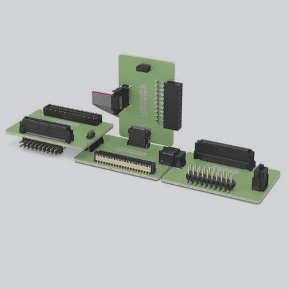
Pin Connection
Pin connections connect circuit board components through corresponding sockets, offering single-pin and multi-pin options.
Advantages: Simple structure, convenient installation.
Disadvantages: Risk of loose connection, breakage.
Spring Connection
Spring connections use the force of springs to connect components, with closed and wing types available.
Advantages: High connection reliability, large contact area.
Disadvantages: High cost, difficulty in automated production.
Clamping Connection
Clamping connections connect components through fixtures, with elastic and pressure clamping options.
Advantages: Secure connection.
Disadvantages: Potential for plate deformation, fracture.
Advantages and Disadvantages of Clamping Connections
Clamping connections offer convenient and quick installation, but they come with drawbacks such as low reliability and susceptibility to breakage and detachment. To ensure a reliable connection, it is crucial to carefully match the elasticity and pressure of the fixture.
Connection Methods for PCB Assembly
-
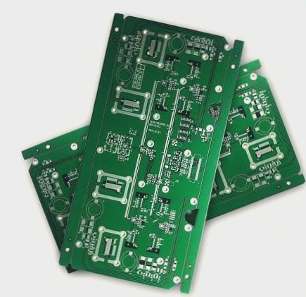
V-Cut
V-Cut, also known as V-Groove, is a thin groove at the junction of two boards that is prone to breaking. When assembling boards, align the edges of the two boards. V-Cuts are usually straight lines without complex curves, so aim for a straight alignment. Leave a 0.4mm gap between the boards for the V-Cut, represented by 2D lines on all layers.
-
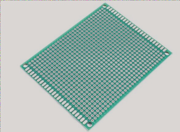
Stamp Hole
Stamp holes are used for connecting irregular panels. This method involves connecting two boards at the edges using a small piece of board with multiple small holes, resembling stamp edges after breaking.
-
Hollow Connecting Strip
Similar to stamp holes, the hollow connecting strip method features a narrower connection area without through holes on both sides. However, it may result in a prominent bump after board breakage, unlike stamp holes where the bump is less noticeable due to the presence of through holes.
Significance of PCB Connection
PCB connections play a vital role in the overall functionality of a machine, facilitating electrical connections between PCBs, external components, and device panels. Optimal selection of connection methods balancing reliability, technology, and cost is a key consideration in PCB design.