Common Causes of PCB Board Welding Defects
1. Solderability of PCB Circuit Board Holes
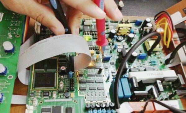
Poor solderability in the PCBA circuit board holes can result in soldering defects, affecting the circuit components’ parameters and causing unstable conduction in both components and internal traces. This can lead to circuit malfunction.
2. Warpage During Soldering
Warpage in both the PCB and its components during soldering can lead to issues like cold solder joints and short circuits due to stress-induced deformation. Temperature imbalances and the weight of larger PCBs can contribute to warping.
3. PCB Circuit Board Design
The design of the PCB directly impacts welding quality. Excessively large boards can increase impedance and costs, while small boards may face heat dissipation challenges. Optimization in PCB design is crucial, including minimizing EMI interference, securing heavy components, considering heat dissipation, and arranging components parallelly.

Best Practices for PCB Handling
- Minimize the distance between high-frequency components to reduce EMI interference.
- Secure heavy components with brackets before soldering.
- Consider heat dissipation for heating components and distance heat-sensitive components from heat sources.
- Arrange components as parallel as possible for easy welding suitable for mass production.
During PCB assembly, proper handling is crucial to avoid compromising solder joints of components like BGAs and chip capacitors. Avoid one-handed PCB handling for larger, heavier boards with such components to ensure quality.
Common Risks of One-Handed PCB Handling
- Using one hand for PCB handling can compromise solder joints of BGAs, chip capacitors, and chip resistors.
- During PCB circulation, individuals often unconsciously use one hand, posing quality risks.
Installation of Screws
Installation of screws on PCBA can lead to component surface deformation, stressing solder joints and increasing the risk of cracks.
If you have any PCB manufacturing needs, feel free to contact us.


