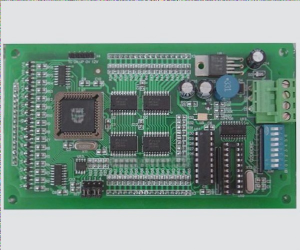
2. In simple terms, this involves applying a suitable stimulus to the PCBA and measuring whether the output response meets specified requirements.
3. Typically, this refers to the PCBA function test conducted after the board is powered on.
4. The content of the PCBA function test includes measuring functional parameters such as voltage, current, power, power factor, frequency, duty cycle, and position determination.
5. PCBA functional testing encompasses analog, digital, memory, RF, and power circuits, with different testing strategies commonly employed.
6. The testing process includes a significant number of essential functional paths and structural verifications to ensure that no hardware errors exist, addressing gaps from previous testing phases.
7. This requires continuously applying numerous analog/digital stimuli to the PCBA while simultaneously monitoring an equivalent number of analog/digital responses and fully controlling the execution of the tests.
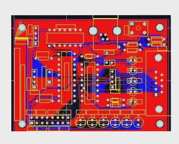
1. There are various forms of PCBA functional test systems and equipment, each with its own advantages and disadvantages regarding cost, time, effectiveness, and maintainability.
2. **PCBA Functional Test Equipment**
3. **Model Testing System**
4. Theoretically, the simplest method to test a device’s function (circuit board or module) is to place it within the same model system or subsystem as the actual environment and observe whether it operates normally. If it does, we can be assured of its functionality. If it does not, technicians will inspect the device in hopes of identifying the failure’s cause to inform maintenance. However, this plug-and-play power-up approach has numerous shortcomings and is rarely effective, though it can sometimes serve as a supplementary method to other testing schemes.
5. **Test Bench**
6. A test bench serves as a conventional testing environment, comprising the stimulus/response interface with the device under test, along with the test sequence and control specified by particular test procedures. Excitation and response are typically supplied by standard power supplies and experimental instruments, specialized switches, loads, and custom electronic equipment (such as digital excitation). The fixture is a crucial component, ensuring the correct signal path and connection to the device under test. Often, the fixture is customized for each application and requires manual setup. The testing process and control are generally performed manually, occasionally aided by a PC, and are governed by written agreements or procedures. The test bench is linked to a specific product, providing a cost-effective and straightforward solution, though it lacks flexibility when handling multiple products.
7. **Dedicated Test Equipment**
8. In theory, dedicated test equipment automates the operations of the test bench. The core of this system is usually a computer, managed by a specialized bus and some programmable instruments. Factors such as speed, performance, availability, and cost influence the selection of instrument buses and structures. Various instruments and general equipment are housed in one or more vertical chassis and connected to the device under test. With automated processing, setup time, testing duration, and overall operation are typically faster and easier compared to manual test benches. Dedicated test equipment can be expanded to accommodate a range of performance requirements and is commonly utilized in production or repair centers. The most evident consideration with dedicated test equipment is the overall cost, which encompasses equipment investment, operating expenses, and program development.
9. **Automatic Test Equipment**
10. General Automatic Test Equipment (GPATE, or ATE for short) represents a highly advanced and flexible solution capable of addressing the testing needs of various products and programs. System integration, signal connectivity flexibility, value-added software and hardware, test-oriented languages, and graphical user interfaces are key distinctions between ATE and dedicated test equipment. Besides full instrument integration, ATE also offers superior solutions for signal routing and connections. In most cases, the ATE’s dedicated backplane includes an analog bus, enabling direct connection of instruments to any pin without complicating the internal and external leads. This flexibility often extends to combining analog and digital channels, allowing users to connect digital or analog stimuli at will and measure any pin of the receiver. Consequently, not only is the cost greatly reduced, but implementing test programs becomes significantly easier. Depending on the control modes, ATE can be categorized into: manual control PCBA function tests, semi-automatic control PCBA function tests, and fully automatic control PCBA function tests. With the rapid advancement of technology, many current PCBA functional tests now utilize fully automatic testing solutions to minimize production costs and enhance efficiency. Currently, for some simpler tested boards, manual or semi-automatic test methods are still employed to simplify design and reduce production costs.
—

