
Understanding PCB Heating Issues
-
What Causes PCB Overheating?
Factors like voltage, current, electrical resistance, and thermal conductivity can lead to PCB heating issues. Understanding PCB current and temperature distribution is crucial for effective troubleshooting.
-
Example Scenario
When voltage is applied to a conductive plate, resistive losses occur, leading to heating. Natural convection helps in cooling the plate, creating a complex heat transfer problem.
Problem Type: Plane-parallel multiphasic problem involving DC electric field and stationary heat transfer.
-
Given Parameters
Sheet thickness (d): 0.035 mm
Material resistance (ρ): 2·10^-8 Ohm·m
Current (I): 10 A
Thermal conductivity coefficient (λ): 380 W/K m
Convection coefficient (α): 10 W/K m² -
Task
Calculate temperature and potential distribution in a conductive sheet based on the given parameters.
PCB Heating Solutions
-
Resolving Resistive Losses
By calculating resistive losses in the DC problem and transferring them to the heat transfer scenario, effective solutions can be devised.
The plate’s cooling by convection can be modeled using heat sink equations, considering external temperature and convection coefficients.
-
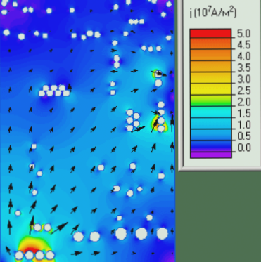
Current and Temperature Distribution
Visual representations of current and temperature distribution in PCBs help in understanding and optimizing electronic circuits.
Current Distribution:

Temperature Distribution: <img alt=”Temperature distribution in the printed circuit board” src=”https://www.wellcircuits.com/wp-content/uploads/9/f3727546-aaad-11ee-baa3-705ab6a7e753/628c3b6f283c6.png</p>
-
Reflow Soldering Process
1. Soldering Principle: Solder paste application, heating, and cooling process for effective PCB component connection.
2. Three Soldering Components: Welding consumables, PCB parts, and heating equipment play crucial roles in the soldering process.
Craft Zone: Detailed stages like preheating, flux removal, melting, reflow, and solidification ensure proper soldering outcomes.
Preheating Zone: Focus on preheating parameters to achieve equilibrium and prevent solder paste issues during reflow soldering.
Reflow Soldering Process and Common Defects
1. Preheating Phase
- Focus: Minimize thermal shock to components
- Purpose: Prevent damage to components like multilayer ceramic capacitors due to excessive temperature, which can lead to cracks and solder spatter. Maintain a temperature below 140 degrees to reduce thermal shock.
- Function and Features: Ensure gradual heating of circuit boards and parts at a slope of 1-3 degrees per second, with a maximum temperature controlled below 140 degrees to reduce thermal shock.
2. SOAK Constant Temperature Area
- Focus: Temperature equalization time
- Purpose: Ensure complete drying of solder for reflow, act as a flux activator to remove metal oxides, and prepare for reflow by reducing surface tension.
- Function and Features: Achieve uniform heating of parts and PCB, eliminate local temperature differences, and prepare surfaces for reflow. The temperature ranges from 140 to 183 degrees for about 45% of the time.
3. REFLOW Reflow Zone
- Focus: Maximum reflow temperature
- Purpose: Melt solder in paste, wet pads and components, and ensure quality reflow soldering by exceeding the melting point temperature by 20-40 degrees.
- Function and Features: Achieve full-scale thermal remelting with a peak temperature between 205-230 degrees, ensuring proper wetting and preventing PCB deformation and part cracking.
4. Cooling Zone
- Focus: Cooling slope
- Purpose: Solidify solder for good electrical contact, prevent decomposition products from affecting joints, and maintain even cooling to avoid poor adhesion.
- Function and Features: Utilize cooling air blowers to evenly cool PCB and parts, keeping the temperature below 120 degrees with a cooling rate around -4 degrees per second.
Common Welding Defects and Solutions
1. Short Circuit Between Solder Balls
- Cause and Countermeasure:
- – Excessive solder paste: Reduce amount and adjust steel plate thickness.
- – Inaccurate printing: Ensure precise printing and adjust steel sheet accordingly.
- – High squeegee pressure: Lower pressure to avoid short circuits.
2. Air Welding SMD Parts with Feet
- Cause and Countermeasure:
- – Uneven parts or solder balls: Check and adjust flatness.
- – Insufficient solder paste: Increase paste amount and adjust steel plate thickness.
- – Lack of wetting: Ensure proper wetting of parts and legs.
3. Airless Welding of SMD Parts without Legs
- Cause and Countermeasure:
- – Incorrect solder pad designs: Separate pads to prevent solder bridging and ensure appropriate size.
Common Soldering Defects and Solutions:
-
Uneven Heating and Insufficient Solder Paste:
Ensure uniform heating across parts and increase solder paste amount.
-
Poor Tin Adhesion:
Verify parts meet tin adhesion requirements for optimal performance.
-
SMD Parts Drifting:
Address uneven heating, tin pad separation, and use parts with superior tin properties.
Reflow Method: Preheat to 170°C before reflow.
-
Tombstone Effect:
Prevent part displacement due to gravity or molten tin effects by ensuring proper soldering board design and using parts with matching tin properties.
Control heating rates and preheat to 170°C before reflow.
-
Cold Solder Joints:
Address low reflow temperatures and short reflow times by using minimum reflow temperature of 215°C and ensuring solder paste melts for at least 10 seconds.
Check pin behavior and inspect tin pad consumption.
-
Granular Solder Joints:
Correct low reflow temperatures and short reflow times with a higher reflow temperature (above 215°C) and longer reflow times (at least 10 seconds above 183°C).
Use clean, fresh solder paste to avoid contamination.