Gerber files are a widely recognized data format in the PCB industry, acting as an intermediary for PCB design and manufacturing. They primarily consist of coordinates and D-codes: coordinates define the length of graphics, while D-codes determine the size and shape of the graphics. Additional photoplotting instructions control the drawing of lines or solder pads. During the evolution of Gerber, two formats emerged: RS-274-D and RS-274-X. The RS-274-D format separates the coordinate and D-code files, while RS-274-X combines both into a single file, including extra parameters that enhance features such as polygon filling, positive/negative image combinations, custom D-codes, and more. It also defines rules for embedding aperture tables within GERBER data files.
Commonly Used D-Codes and Their Functions
D-codes are instructions for the photoplotter. The first three D-codes control the movement of the working table in the X-Y direction.
D01 (D1): Opens the shutter and simultaneously moves the working table to the specified X-Y coordinates.
D02 (D2): Closes the shutter and simultaneously moves the working table to the specified X-Y coordinates.
D03 (D3): Moves the working table to the designated X-Y position with the shutter closed, then quickly opens and closes the shutter to create an exposure point.
D01 is the command for “drawing” a line, while D02 is the command for moving the table without exposing any film. D01 and D02 correspond to lowering and raising the pen on the plotter, respectively.
D03 is the flash command. With the shutter closed, the working table is moved. When the desired X-Y coordinates are reached, the shutter is opened and closed, leaving the image of the aperture on the film. This flash command is an efficient method for imaging the numerous pads found on most circuit boards.

D01, D02, and D03 commands follow their corresponding coordinate data. For example, in the following sequence:
X0Y0D02*
X450Y330D01*
X455Y300D03*
The table moves to the position (0,0) with the shutter closed. Then, a line is drawn from (0,0) to (450,330) using the D01 command. The flash occurs at (455,300).
Aperture Marks, D-Codes, and D10-D999
Unlike D01, D02, and D03, D10 to D999 represent data rather than commands, and they are used to mark apertures or the aperture wheel. Early photoplotters utilized aperture wheels with 24 slots, which defined line thickness and shapes for flashing or drawing.
The following table shows the correspondence between optical apertures and D-codes in early photoplotters:

It can be seen that the D10 to D19 sequence is normal, followed by D70 and D71, with D20 appearing in the 13th position. The range extends from D20 to D29. By D30, the aperture should be 23, with D72 and D73 inserted before D30. Most optical plotting and CAM software require you to input aperture information (shape and size) based on the D-code. Several programs may also require input based on the aperture number, which may necessitate rearranging the corresponding table.
There is a special range of D-codes between D3 and D9, used for representing special line segments, such as dashed lines. These are rarely used today and are only supported by some older photoplotters.
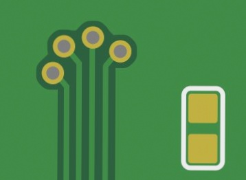
Without the D-code, copper, solder pads, or holes would lack defined shape and size, as illustrated in the diagram below:

The outdated Gerber RS-274-D standard format for layout data requires a separate D-code list, which contains information about geometric shapes (commonly circles, rectangles, and annuli) and aperture sizes.
We recommend using the extended Gerber format (RS-274-X), where the D-code list is stored in the header of each record. This approach facilitates automated processing and ensures that no information is lost during data transfer.
If you have any questions regarding PCBs or PCBA, please feel free to contact me at info@wellcircuits.com.


