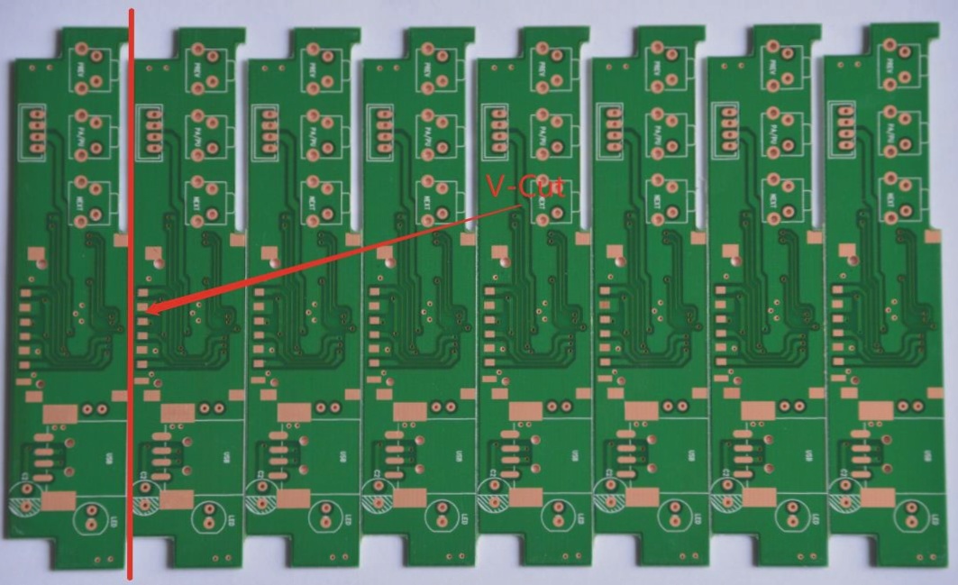
The Importance of V-Cut in PCB Manufacturing
- When PCB manufacturers create a V-cut on the board, it aids in the subsequent assembly process, making it easier to separate individual boards.
- Manual separation of PCBs is challenging due to their strength, highlighting the necessity of pre-cut V-cuts to prevent component damage.
- V-cut design allows for efficient de-paneling of circuit boards, streamlining the assembly process.
- After assembly, dividing the panel into individual boards is crucial for further production steps.
One of the primary purposes of V-cut design is to facilitate the de-paneling process post-PCB assembly. This design feature enables operators to separate boards easily, enhancing efficiency and reducing the risk of component damage.
The Process of V-Cut Splitting
- Utilizing a V-Cut board splitter or scoring machine simplifies the separation of PCBs.
- Automatic scoring machines align with pre-cut V-shaped grooves on the PCB, allowing for precise separation with a push of a button.
- Manual snapping of V-cut PCBs is discouraged due to the risk of component damage and reduced product reliability.
While V-Cut splitting can be done manually, using a scoring machine is the recommended method to ensure precision and avoid potential issues with electronic components.
Limitations of V-Cut Design
- V-Cut designs are limited to straight lines and may not be suitable for complex cutting paths.
- Thin PCBs (<1.0mm) should avoid V-Cut designs to maintain structural integrity and prevent bending during assembly.
- Poorly designed V-Cut positions can lead to deformation during high-temperature processes, affecting soldering operations.
While V-Cut designs offer advantages in PCB manufacturing, it is essential to consider their limitations, especially concerning board thickness and potential deformation during reflow processes.
Understanding V-Cut in PCBs
V-Cut plays a vital role in simplifying the de-paneling process and enhancing production efficiency. By utilizing V-Cut designs effectively, PCB manufacturers can streamline assembly operations and improve overall product quality.
Understanding PCB V-Cut Groove Size and Angle
When determining the size of a V-Cut groove in a PCB, it’s essential to focus on the remaining thickness, which is the material between the two inverted V ports of the groove. This thickness plays a critical role in the board’s resistance to breakage and deformation.
The recommended residual thickness of a V-Cut is typically around 1/3 of the overall board thickness, with a minimum of 0.35mm. Thinner sections increase the risk of premature breakage during manufacturing. On the other hand, the maximum residual thickness should not exceed 0.8mm, as a thicker V-Cut may damage the cutting blade and reduce its lifespan.
The Angle Definition of PCB V-Cut
The V-Cut features various angles, including 30°, 45°, and 60°, with 45° being the most commonly used angle. As the angle increases, more of the board edge is affected, requiring careful positioning of the circuit on the opposite PCB to avoid damage during the cutting process.
A smaller V-Cut angle may allow for better PCB space design but can lead to quicker wear and breakage of the manufacturer’s saw blade. For thicker boards, deeper cuts are needed, often necessitating a larger V-Cut angle. Boards thicker than 1.6mm generally avoid the 30° angle, favoring Router cutting in large-scale production.
While Router cutting can overcome many V-Cut disadvantages, the choice between the two methods often comes down to cost. In the realm of PCB manufacturing, cost-effective and efficient solutions tend to dominate the market, making V-Cut design a popular choice.