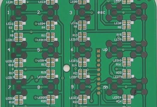
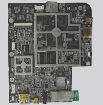
The FCT Test in which the PCBA is powered up is referred to as an FCT. Among the features are voltage, current measurement and control, power factors, frequency and duty ratio, position determination, LED lighting, LED color, sound recognition, temperature, and pressure measurement control, etc.
What’s more essential than adhering to PCB manufacturing’s highest quality requirements is ensuring that your board functions as intended. This necessitates a series of tests to be carried out at different phases, including development, production, and assembly.
There are a variety of functional tests that may be performed on a PCB to ensure that it is working correctly. To enable PCB functional testing, the manufacturer may also need to alter the design of the PCB. Sending the design files back and forth should be simple as long as the manufacturer is aware of your device’s functional specifications and the testing procedures you’ve established. Of course, a cloud-based solution for data access is the ideal option.
Classification of Functional Tests
In order to accommodate a variety of control modes
(1)Manually control functional tests
(2)Semi-automatic control function test
(3)Fully automatic control function test
The early function tests are mostly automated or semi-automatic, with a few exceptions. Manual and semi-automatic methods are still used to simplify the design and lower manufacturing costs. In order to reduce money and increase production efficiency, many functional tests have been automated.
For a different kind of controller:
- A microprocessor controller
- Embedded CPU controllers are also available
- PC controller
- PLC Control
Why Do We Perform Functional Tests?
Manufacturers use functional testing (FCT) to ensure their products are of high quality. Predefined standards for the future use of DUTs are scrutinized throughout the testing process to ensure they are up to snuff. In addition to functional testing, a DUT is recommended to be subjected to undesired conditions in order to see how it responds (e. g. switching off on overvoltage). If a functional item is being manufactured, functional tests are often conducted at the end of the manufacturing line.
How Are Functional Tests Performed?
During functional testing, a DUT’s response to various external stimuli relevant to its intended use is evaluated in great detail. If the anticipated behaviour is met, it passes the test. These are some of the most often cited influences:
- At the electrical inputs (e. g., voltage dips or interruptions)
- Input signals in the form of digital data (e. g. communication messages through KNX, DALI, CAN, I2C, Flexray, etc.)
- (Simulated) user interface operations (e. g., buttons, rotary controls)
- Using sensors to interact (e. g. NFC)
- inclement weather (e. g. high or low temperatures)
Differences From Other Methods Of Testing
Other electrical tests that look for manufacturing flaws by evaluating physical characteristics rather than functional responses (e.g. identification of incorrect soldering by assessing electrical resistances) must be differentiated from functional testing.
In-circuit testing (ICT):
Using specialized needle bed adapters, many test locations may be contacted at the same time to inspect built PCBs.
PBT using a flying probe (FPT):
A few successive test points are performed when inspecting the constructed PCBs using universal flying probe testers.
Functional Testing Requires What?
The industrial FCT Test requires the following hardware and software:
- A test control unit (FCT tester) that manages the DUT’s exposure to external factors and records its responses accurately and in real-time (e. g. our Guardian FCT tester)
- Connecting the DUT (test adapter) to the control unit in a time-efficient or even automated manner is possible with this method (e. g., test adapters by GTS Test Solutions)
- Software for real-time examination of test sequences that may be programmed and executed (e. g., WinGuard)
- Sensors and systems (such as color sensors) are essential for the creation of the necessary environmental circumstances (e. g. climatic chambers)
The FCT Machine (Functional Circuit Test)
Functional Circuit Testing (FCT) is an approach to testing that offers a simulated operating environment for the test target board so that it may operate in predefined states and acquire parameters for each condition in order to validate the UUT. Functional testing of PCBAs is often referred to as PCB testing.
Features
- In order to guarantee long-term performance and balance of action, it is best to choose pneumatic components from well-known brands.
- Drilling precision in high-CNC machining is limited to 0.005MM.
- Slab, guard plate, and needle plate verticality are ensured by a linear bearing guide.
- Preventing mishaps via the use of both hands simultaneously
- You may save time and effort by using a quick clip as a power source with a well-balanced and simple operation.
- In terms of accuracy and throughput, CNC is unmatched.
- Use a linear bearing guide to ensure that the needle point is precisely centered.
- The base of the rack may be changed, allowing for simple adjustment.
PCB Assembly Functional Testing
Before the thermal aging test, a functional test (FCT) is performed. It is used to test the PCBA’s functional performance in a working environment.
Using PCB software, the following steps may be performed:
The PCB assembly is then connected to the PCBA tester by a test technician, who runs the test program and turns on the PCBA. In Visual Basic, our testing system is set up.
The technician then uses the PCBA tester to read the signals from the PCB chips and route them to the test locations on the board.
This is the most efficient method when using an oscilloscope to view the signal levels and voltage values. Using an oscilloscope linked to a computer, our expert may check for signal integrity and see whether voltages are running correctly by seeing if the screen shows okay or NG (not good) and if the PCBA is okay.
There is a complete record of every step of the testing procedure. IC programming or thermal aging are the following steps in the PCB construction if the computer says so. Once our experts have debugged the computer, all PCBA testing is restarted.
In most cases, we recommend functional testing to clients whose PCBs have an area of more than three square meters. It identifies any open connections, damaged components, solder shorts, and other issues with the PCB. PCB manufacturers use it to provide a high level of accuracy in the assembly process.

Your PCB Assembly Benefits from FCT
This is what you’ll gain by working with the FCT:
- The FCT saves the consumer from acquiring expensive testing equipment or hiring a testing business, which is significantly more costly.
- System testing is no longer required. ”
- Everything that may go wrong with the PCB is covered here, including resistance and voltage, as well as communication methods.
- To add serial numbers and calibration factors at this point, manufacturers have the ability to do so.
- Any faults in the PCB’s operating environment are removed during the FCT Test. Monitoring responses at certain moments ensures the product’s operation and guarantees that it will not malfunction. This is critical for customers who may not be able to figure out the problem on their own.
Benefits to Customers of Functional Testing
- In order to save money for the client, functional testing mimics the product’s operational environment, reducing the need for costly testing equipment.
- When costly system testing is not required, the OEM saves a great deal of time and money.
- In order to save time and effort for the OEM, it may do a functional test on anywhere from 50 to 100 percent of the product being delivered.
- Functional testing may be made more productive than system testing by skilled engineers who know how to use it.
- ICT and flying probe tests may be enhanced by functional testing to make the product more reliable and error-free.
- By mimicking the product’s operating context, a functional test ensures that the product functions correctly. The DUT’s environment includes everything that can interact with it, such as the DUT’s power supply or any software loads required for the DUT to operate effectively.
- The PCB is put through its paces by a series of signals and power sources. At certain moments, responses are checked to verify that everything works as it should. The OEM test engineer often creates the standards and test methods that are followed throughout the test. This test is the most effective at identifying incorrect component values, functional issues, and parametric issues.
- Automated functional testing is made possible by test software, which is also known as firmware by production line operators. An externally programmable instrument, such as an I/O board or digital multimeter, is used to connect with the software. An FCT Test may be performed using the instruments connected to the DUT through a fixture and software.
Last Words:
Finally, the FCT Test is performed. Finished PCBs may be passed or failed using this test, and they can then be sent off. It is an FCT’s job to ensure that the manufacturing process is free of faults that might harm the product’s ability to perform properly in a system.
Now that you’ve learned about PCBA functional testing, you should have a better grasp of the process. It might be a frustrating experience for the consumer if the whole PCB fails to operate. For example, the FCT mimics the circuit board’s operational environment and helps you avoid any future mistakes.


