Testing Printed Circuit Boards and Assemblies
- This International Standard specifies methods for testing printed circuit boards and printed circuit assemblies and their associated materials or the bonding strength of parts, regardless of how they are manufactured.
Understanding PCB Electrical Testing
- The standard consists of parts containing information for product designers, technologists, and specialists in the field of test methodology.
- Test methods are grouped according to their use and numbered sequentially according to their development and publication.
Grouping of Tests in the Standard
- R: preparation/conditioning test methods;
- V: visual test methods
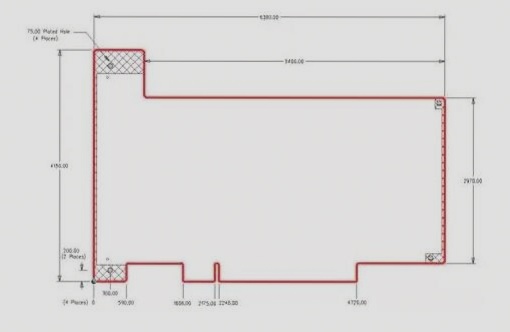
- D: dimensional test methods;
- C: chemical test methods;
- M: mechanical test methods;
- E: electrical test methods;
- N: environmental test methods;
- X: other test methods.
Ensuring Accuracy in PCB Electrical Testing
- Calibration of test equipment must be clearly defined in the quality management documentation.
- Calibration should be done by an accredited organization according to national or international standards.
Interval Between Calibrations
- The interval between calibrations is typically one year, but equipment falling outside the margin of error should be calibrated more frequently.
- Calibration and maintenance information must be recorded for each measuring instrument.
List of Approved Test Methods
- The International Standard contains detailed descriptions of each specific test method with minimal cross-references.
- Methods may refer to universal conditioning methods, such as IEC 61189-1 and IEC 60068, to ensure standardized testing.
Latest Update: The PCB industry is rapidly evolving with the emergence of new materials and technologies, leading to the development of more advanced testing methods to ensure the reliability and performance of printed circuit boards and assemblies. Stay informed about the latest trends and innovations in PCB testing to maintain a competitive edge in the market.
Test Methods for PCB Preparation/Conditioning
The test methods for PCB preparation and conditioning consist of various groups of methods as well as individual tests.
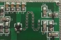
Visual Test Methods
One of the visual test methods is Test 3V01: Visual inspection, 3x magnification. This method involves visually inspecting materials and finished printed circuit boards with a 3-fold magnification as required by technical specifications.
The materials required for this test include:
- An optical device capable of providing 3x magnification.
- A reference optical device capable of 10x magnification.
Test Equipment and Materials
For conducting the test, specific materials and equipment are necessary:
a) A glow wire made of nickel and chromium (80%/20%) with a diameter of 4 mm.
b) A sheathed thin wire thermocouple for measuring the temperature of the hot wire.
c) The sheath material must withstand a temperature of at least 960°C.
d) A temperature/voltage measuring instrument with 1% accuracy.
e) The hot wire is heated electrically, requiring a current range of 120-150 A.
f) The test apparatus should ensure the glow wire is horizontal, applying a force of 0.8 to 1.2 N to the specimen.
Steps for PCB Electrical Testing
1. Precondition the test specimen in an air circulation oven at (124 ± 2)°C for 24 hours, followed by stabilization in a desiccator over anhydrous calcium chloride at room temperature for 4 hours.
2. Specify the orientation of the test specimen if other than vertical.
3. Calibrate the thermocouple at 960°C using a silver foil method.
4. Recalibrate the thermocouple every five measurements to account for changes.
5. Ensure the thermocouple can follow the hot wire’s movement due to thermal expansion.
6. Mount the test piece to minimize heat loss to the test fixture.
7. Apply the glow wire to the part of the test specimen subjected to thermal stress, at least 15 mm below the top edge.
8. Heat the glow wire to the specified temperature, ensuring stability for at least 60 seconds before starting the test.
For more information on using glow wire in PCB electrical testing, visit wellcircuits.com.
Printed Circuit Board Inspection Protocol
- Number of samples required for testing
- Duration from applying the glow wire to ignition
- Duration from applying the glow wire to flame extinction
- Maximum flame height measurement criteria
- Observations on burning or smoldering of the test specimen
- Assessment of burning or smoldering cessation post glow wire removal
Key Points on PCB Testing
- Importance of tester training and lab safety knowledge due to flammability hazards
- Small flammability tests offer insights into material properties
- Fire resistance evaluation of equipment with PCBs requires specific testing
- IEC committees exploring cone calorimeter for fire resistance testing