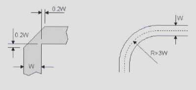
2. For radio frequency lines, right-angle corners can cause discontinuities, which can lead to high-order modes that negatively impact radiation and conduction performance.
3. When an RF signal line turns at a right angle, the effective width at the corner increases, resulting in impedance discontinuities and signal reflections.
4. To reduce discontinuities at corners, use either chamfering or rounding techniques.
5. The radius of the arc should be sufficiently large, generally ensuring R > 3W.

1. Acute and Right-Angle Routing
2. Acute-angle wiring is generally prohibited in PCB design. Right-angle wiring is also typically avoided as much as possible, as it is considered a standard for evaluating wiring quality. So, what impact does right-angle wiring have on signal transmission?
3. In principle, sharp and right-angled turns in wiring can alter the trace width, leading to impedance discontinuities. Variations in trace width cause impedance changes, which can result in signal reflections when the effective width of the trace changes.
4. During routing, any change in line width will affect the impedance of the trace. A microstrip line, consisting of a ribbon wire over a ground plane with a dielectric in between, has its characteristic impedance determined by the dielectric constant, line width, and distance from the ground plane. If these parameters are controlled, the characteristic impedance can be maintained within ±5%.
5. A stripline consists of a copper trace sandwiched between two conductive planes within a dielectric. If the trace thickness, width, dielectric constant, and distance between the ground planes are controlled, the characteristic impedance can be controlled with an accuracy of ±10%.
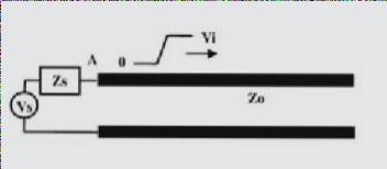
6. Impedance discontinuities are influenced by acute angles, right angles, obtuse angles, rounded corners, and straight lines. When a driver sends a signal through a transmission line, the signal amplitude depends on the voltage, the internal resistance of the buffer, and the impedance of the transmission line. The initial voltage at the driver end is determined by the voltage division between the internal resistance and the line impedance.

1. Reflection coefficient, where -1 ≤ ρ ≤ 1.
2. No reflection occurs when ρ = 0.
3. When ρ = 1 (Z2 = ∞, open circuit), total positive reflection occurs.
4. When ρ = -1 (Z2 = 0, short circuit), total negative reflection occurs.
5. The initial voltage is the source voltage ( V_s ) (2V) divided by ( Z_s ) (25 ohms) and the transmission line impedance (50 ohms).
6. The subsequent reflectivity of ( V_{text{initial}} = 1.33V ) is calculated using the reflection coefficient formula.
7. The reflectivity at the source end is calculated using the source end impedance (25 ohms) and the transmission line impedance (50 ohms) according to the reflection coefficient formula, resulting in -0.33.
8. The reflectivity at the terminal is calculated using the terminal impedance (infinity) and the transmission line impedance (50 ohms), resulting in 1 according to the reflection coefficient formula.
9. We obtain this waveform by superimposing the initial pulse waveform based on the amplitude and delay of each reflection.
10. Impedance mismatch is the ultimate cause of poor signal integrity.
11. Due to connections, device pins, trace width changes, trace bends, and vias, impedance variations are inevitable, leading to unavoidable reflections.

—
Is there any reason besides reflection? The influence of right-angle routing on the signal is mainly reflected in three aspects.
1. The corner can be equivalent to a capacitive load on the transmission line, which slows down the rise time.
2. Discontinuous impedance will cause signal reflection.
3. EMI is generated at right angles.
4. There is another perspective: acute angles can lead to corrosion residues in the production process, making them difficult to process. However, with current processing technology, this issue is minimal and should not be a significant concern.
The parasitic capacitance caused by the right angle of the transmission line can be estimated using the following empirical formula: C = 61W(εr)^1/2/Z0. In this formula, C represents the equivalent capacitance of the corner (unit: pF), W is the width of the line (unit: inch), εr is the dielectric constant of the medium, and Z0 is the characteristic impedance of the transmission line. For example, for a 4-mil, 50-ohm transmission line (with εr = 4.3), the capacitance introduced by a right angle is approximately 0.0101 pF. Consequently, the rise time change caused by this can be estimated as: T10-90% = 2.2 * C * Z0 / 2 = 2.2 * 0.0101 * 50 / 2 = 0.556 ps. Calculations show that the capacitance effect due to right-angle traces is extremely small.
As the line width of the right-angle trace increases, the impedance at that point will decrease, leading to some signal reflection. We can compute the equivalent impedance after the line width increases using the impedance calculation formula from the transmission line chapter, and then determine the reflection coefficient using the empirical formula: ρ = (Zs – Z0) / (Zs + Z0). Typically, impedance changes caused by right-angle wiring range between 7% and 20%, resulting in a reflection coefficient of about 0.1. Furthermore, as shown in the figure below, the impedance of the transmission line changes within a short distance of W/2 and then returns to its normal impedance. This impedance variation is extremely brief, often within 10 picoseconds. Such rapid and minimal changes are almost negligible for general signal transmission.
Many people believe that right-angle routing is prone to electromagnetic wave transmission and EMI generation, which has led to the perception that right-angle routing should be avoided. However, many practical test results demonstrate that right-angled traces do not produce significant EMI compared to straight lines. Although current instrument performance and test levels may restrict test sensitivity, this observation suggests that the radiation from right-angle routing is less than the measurement error of the instruments. In general, right-angle routing is not as problematic as often perceived. In the context of non-RF and high-speed circuit board designs, effects such as capacitance, reflection, and EMI from right-angle routing are rarely noticeable in TDR tests. High-speed circuit board designers should focus on layout, power/ground design, routing, and vias, among other aspects.
Of course, although the impact of right-angle routing is not severe, it does not imply that it should be used indiscriminately. Attention to detail is a fundamental quality for every engineer. With the rapid advancement in digital circuits, PCB engineers will increasingly deal with higher signal frequencies. In RF design above 10 GHz, even small right angles may become significant issues in high-speed printed circuit boards.
—
